
Light-emitting Device

A technology for light-emitting devices and light-emitting components, which is used in transportation and packaging, thin material processing, electrical components, etc., to achieve the effects of preventing the decline of luminous efficiency, preventing corrosion, and having high thermal conductivity.

Inactive Publication Date: 2012-11-28
AGC INC
View PDF7 Cites 2 Cited by
  • Summary
  • Abstract
  • Description
  • Claims
  • Application Information

AI Technical Summary

Problems solved by technology

[0007] However, even if it is covered with resin, moisture or corrosive gas will easily enter from the resin or the interface between the silver conductor layer and the resin, and the silver conductor layer will be corroded over time, so there is a problem of long-term reliability.

Method used


Image

  • Light-emitting Device
  • Light-emitting Device
  • Light-emitting Device

Examples


Embodiment

[0077] A green sheet for forming a lower ceramic layer was produced by the following method. That is, to form SiO in mole % 2 60.4%, B 2 o 3 15.6%, Al 2 o 3 6%, CaO 15%, K 2 O is 1%, Na 2 Glass raw materials were blended and mixed at a composition of 2% O, and the mixed raw materials were put into a platinum crucible and melted at 1550 to 1600° C. for 60 minutes, and then the molten glass was poured out and cooled. The obtained glass was pulverized in ethanol for 20 to 60 hours using an alumina ball mill to obtain glass powder. The D of the powder was measured using SALD2100 manufactured by Shimadzu Corporation (Shimadzu Corporation). 50 , the result is 2.5 μm. The softening point Ts (unit: °C) and crystallization peak temperature Tc (unit: °C), as a result, Ts was not clear, and Tc was 850 °C.

[0078] Expressed in mass percent, according to the ratio of 40% for the above-mentioned glass powder and 60% for the aluminum oxide powder AL-45H produced by Showa Denko Cor...

example 1~ example 18

[0080] A glass-ceramic paste for forming an upper ceramic layer was produced by the following method. That is, each raw material is blended and mixed to form SiO 2 to ZrO 2 Compositions shown in mol % in the columns above, each mixed raw material was put into a platinum crucible and melted at 1550-1600° C. for 60 minutes, and then poured out the molten glass and cooled. The obtained glass was pulverized in ethanol for 20 to 60 hours using an alumina ball mill, and the same operation as above was performed to obtain glass powder. The D of each obtained glass powder was measured using SALD2100 manufactured by Shimadzu Corporation. 50 (unit: μm). In addition, the softening point Ts (unit: °C) and crystallization peak temperature Tc (unit: °C) were measured using a thermal analysis device TG-DTA2000 manufactured by Bruker AXS Co., Ltd. at a heating rate of 10 °C / min to 1000 °C. For the glass powder of each composition, the measured D 50 Each value of (unit: μm), softening poi...


PUM

PropertyMeasurementUnit
thicknessaaaaaaaaaa
particle sizeaaaaaaaaaa
thicknessaaaaaaaaaa

Abstract

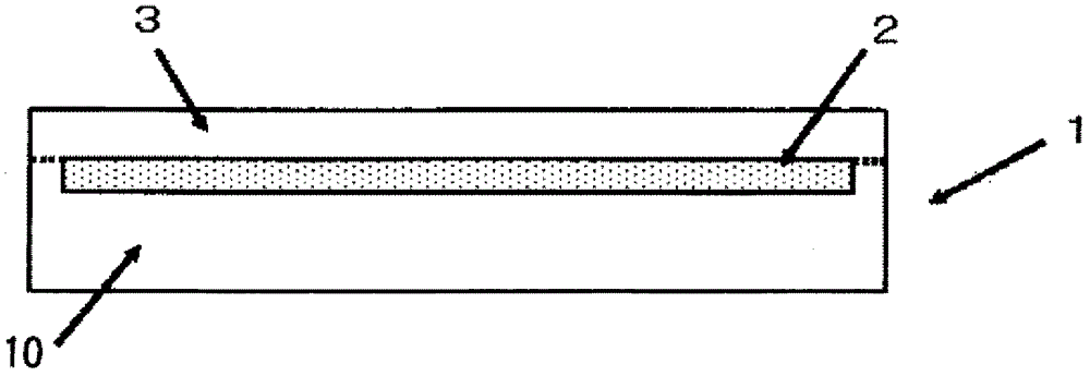
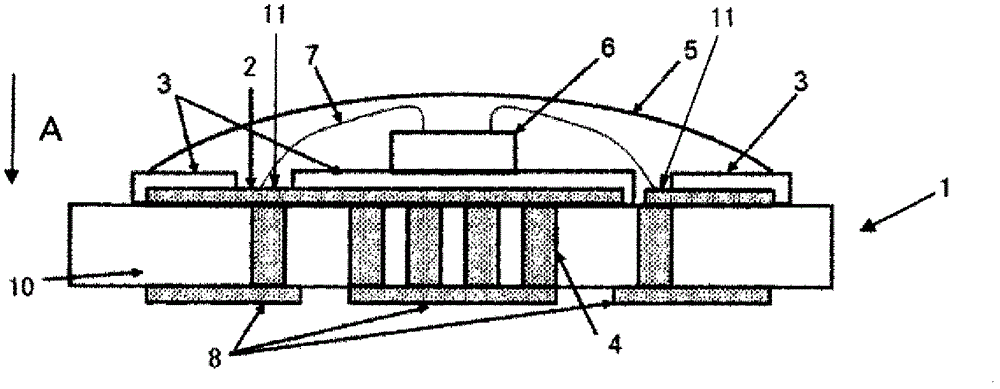
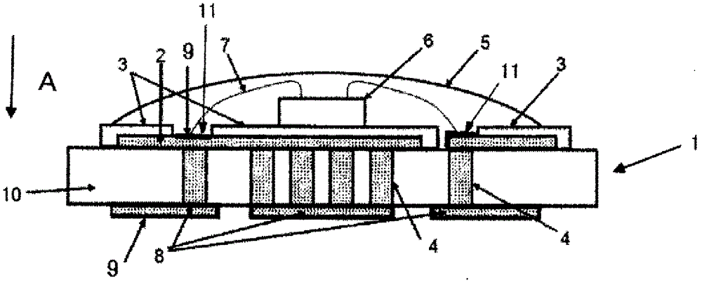
Disclosed is a light-emitting device which comprises a conductive layer for light reflection and has improved light extraction efficiency and excellent heat dissipation properties, said conductive layer for light reflection having a high optical reflectance that is not decreased much by corrosion. Specifically disclosed is a light-emitting device which comprises: a ceramic substrate which has a lower ceramic layer, a conductive layer for light reflection that is formed in a desired region on the surface of the lower ceramic layer, and an upper ceramic layer that is formed so as to cover at least a partial region of the conductive layer for light reflection; and a light-emitting element that is arranged on top of the upper ceramic layer of the ceramic substrate. The light-emitting device is characterized in that the upper ceramic layer has a thickness of 5-100 [mu]m. The upper ceramic layer may be configured of a glass-ceramic material that contains, in mass%, 40-60% of a glass component and 40-60% of a ceramic filler component.

Description

technical field [0001] The present invention relates to a light-emitting device for forming lighting equipment including light-emitting diode (hereinafter also referred to as LED) devices, high-brightness light-emitting diode backlights, display-related light sources, automotive lighting, decorative lighting, sign and advertisement lighting, and information display applications And the mounting substrate used in the light emitting device. Background technique [0002] In recent years, as light-emitting devices such as LEDs have become brighter and whiter, light-emitting devices using LEDs have come to be used as backlights for mobile phones, large-sized liquid crystal televisions, and the like. In order for LED lights to be suitable for various purposes, it is important to obtain a white glow. [0003] As a method of realizing white light emission with LED lamps, the following methods can be cited: the method of using three LED chips that emit blue, green, and red light res...

Claims


Application Information

Patent Timeline
Patent Type & Authority Applications(China)
IPC IPC(8): H01L33/60H01L33/64
CPCH01L2924/0002H01L33/647H01L33/486H01L33/60H01L33/642H01L2924/181H01L2224/48091H01L2224/48227H01L2224/45144Y10T428/24331H01L2924/00012H01L2924/00014H01L2924/00H01L33/48H01L33/64
Inventor 中山胜寿冈田利久大崎康子
Owner AGC INC
Learn More