Device and method for measuring radar reflection characteristic of plasma coating material

A plasma and radar reflection technology, which is used in measurement devices, analytical materials, and material analysis using radiation diffraction. Measure the effect of accurate, uniform plasma coating

Active Publication Date: 2012-12-05
XIDIAN UNIV
View PDF2 Cites 20 Cited by
  • Summary
  • Abstract
  • Description
  • Claims
  • Application Information

AI Technical Summary

Problems solved by technology

[0015] 1) Plasma cannot cover the surface of the material to be tested
The plasma generated by this type of device is located inside the vacuum chamber, and the front and rear are blocked by quartz observation windows, so the plasma inside cannot be coated on the surface of the mater

Method used


Image

  • Device and method for measuring radar reflection characteristic of plasma coating material
  • Device and method for measuring radar reflection characteristic of plasma coating material
  • Device and method for measuring radar reflection characteristic of plasma coating material

Examples


Embodiment 1

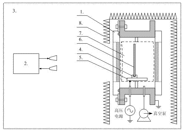
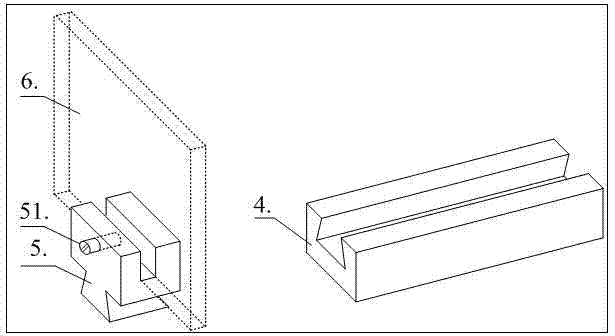
[0034] A device for measuring radar reflection characteristics of plasma-coated materials, including: a large-area uniform non-magnetized plasma generating unit 1, a radar scattering cross-section measuring mechanism 2, a microwave anechoic chamber 3, a supporting guide rail 4, a supporting slider 5, and a material plate to be tested 6 , microwave absorbing material 8, large-area uniform non-magnetized plasma generating unit 1, radar cross-section measuring mechanism 2 fixed in the microwave anechoic chamber 3, large-area uniform non-magnetized plasma generating unit 1 surrounded by a wave-absorbing material 8 in a space , the wave-absorbing material 8 has a window, so that the measured material plate 6 of the large-area uniform non-magnetized plasma generating unit 1 faces the radar cross-section measuring mechanism 2 directly.

Embodiment 2

[0036] refer to figure 1, a device for measuring radar reflection characteristics of plasma-coated materials, including: a large-area uniform non-magnetized plasma generating unit 1, a radar cross-section measuring mechanism 2, a microwave anechoic chamber 3, a supporting guide rail 4, a supporting slider 5, and a material plate to be tested 6. Wave-absorbing material 8, large-area uniform non-magnetized plasma generating unit 1, radar cross-section measuring mechanism 2 fixed in microwave anechoic chamber 3, large-area uniform non-magnetized plasma generating unit 1 surrounded by wave-absorbing material 8 in a space Inside, the wave-absorbing material 8 has a window, so that the measured material plate 6 of the large-area uniform non-magnetized plasma generating unit 1 directly faces the radar cross-section measurement mechanism 2, and the measured material plate 6 is fixed by the supporting guide rail 4 and the supporting block 5. In the cavity of the large-area uniform non-...


PUM


Abstract

The invention discloses a device and a method for measuring the radar reflection characteristic of a plasma coating material. The device comprises a large-area uniform unmagnetized plasma generation unit, a radar cross section measurement mechanism, a microwave unreflected chamber, a supporting guide rail, a supporting sliding block, a measured material plate and a wave-absorbing material, wherein the large-area uniform unmagnetized plasma generation unit and the radar cross section measurement mechanism are fixed in the microwave unreflected chamber; the large-area uniform unmagnetized plasma generation unit is surrounded in a space by the wave-absorbing material; and the wave-absorbing material is provided with a window, so that the measured material plate of the large-area uniform unmagnetized plasma generation unit directly faces the radar cross section measurement mechanism. By the device and the method, plasma can be coated on the surface of a measured material, and the adjustment of the thickness of the plasma and the weakening of the radar echo reflection of a body are further realized, so that the development of the experimental measurement of the radar reflection characteristic of the plasma coating material is met.

Description

technical field [0001] The invention belongs to the technical field of microwave / radar detection, and relates to a device and method for measuring radar reflection characteristics of plasma-coated materials, which can be used to uniformly coat plasma on a material to be tested and measure its radar reflection characteristics. Background technique [0002] As a special dispersion medium, plasma has unique absorption, reflection and scattering properties for electromagnetic waves, which is very different from various conventional materials. Generally, during the high-speed re-entry process of targets such as various spacecraft and warheads, plasma will be produced to cover itself due to friction and high temperature, and its surface is equivalent to a composite material covered with plasma, thereby changing the radar reflection characteristics of the target itself ( Usually to attenuate radar echoes). Therefore, the study of materials and target characteristics under plasma c...

Claims


Application Information

Patent Timeline
IPC IPC(8): G01N23/20G01N22/00G01N21/00G01N1/28
Inventor 谢楷赵良秦永强李小平刘彦明刘东林
Owner XIDIAN UNIV
Why Eureka
Try Eureka