Phase Locked Loop (PLL) With Analog And Digital Feedback Controls

A control loop and circuit technology, applied in the direction of automatic power control, electrical components, etc., can solve a lot of problems

Active Publication Date: 2012-12-05
TEXAS INSTR INC
View PDF15 Cites 6 Cited by
  • Summary
  • Abstract
  • Description
  • Claims
  • Application Information

AI Technical Summary

Problems solved by technology

Another disadvantage is the size of the capacitor CCT, which

Method used


Image

  • Phase Locked Loop (PLL) With Analog And Digital Feedback Controls
  • Phase Locked Loop (PLL) With Analog And Digital Feedback Controls
  • Phase Locked Loop (PLL) With Analog And Digital Feedback Controls

Examples


Embodiment Construction

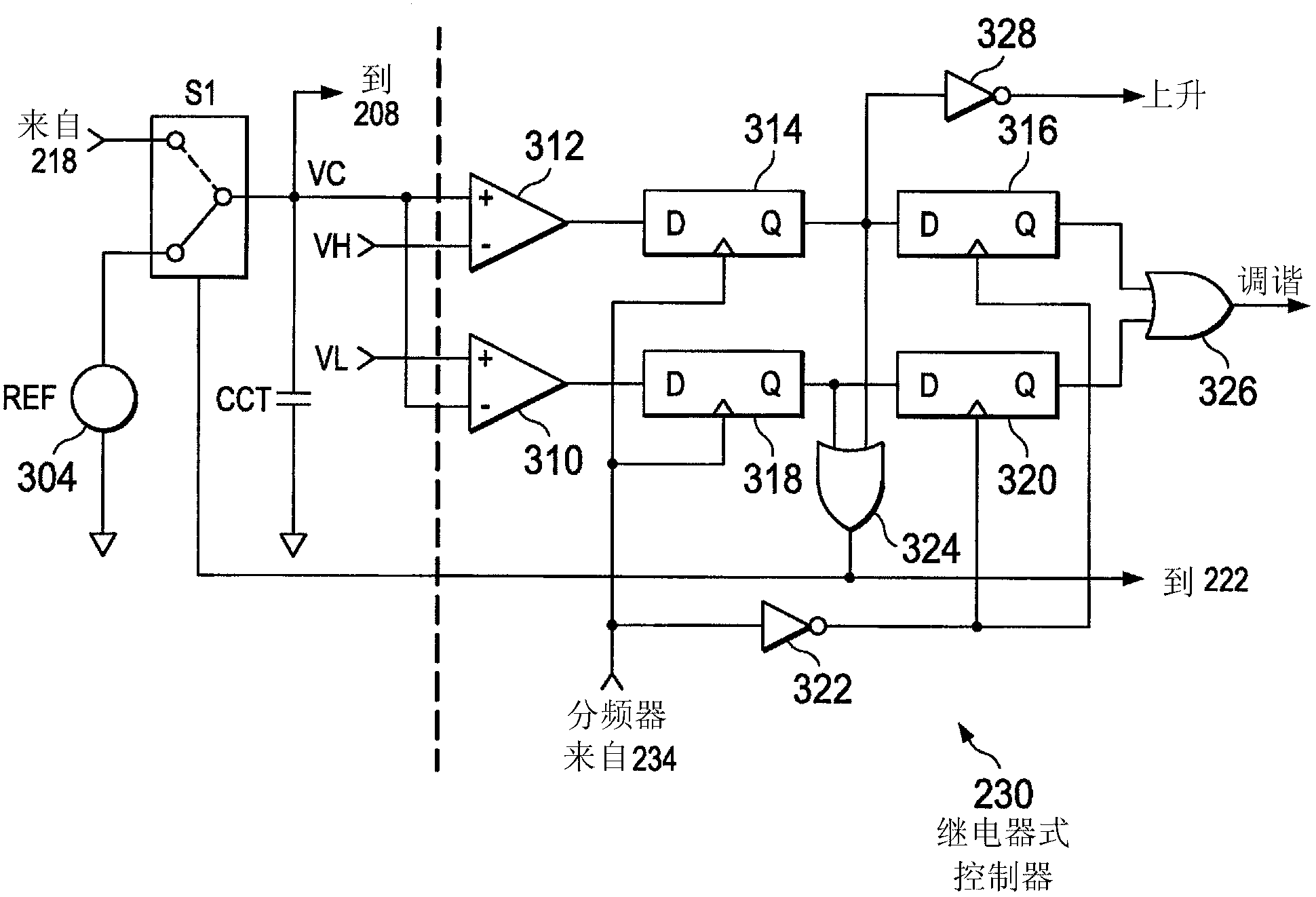
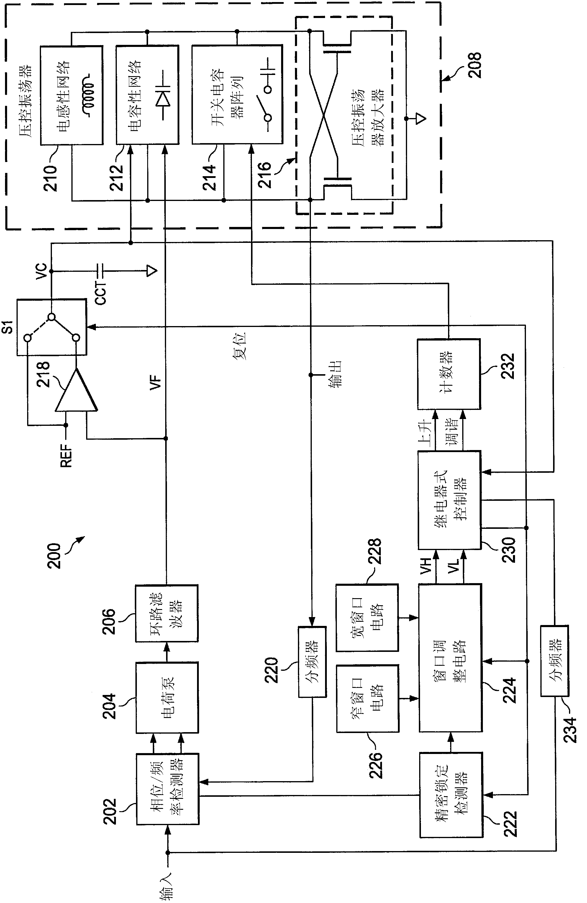
[0022] figure 2 , reference numeral 200 generally designates a PLL according to an example embodiment of the invention. PLL 200 generally consists of PFD 202, charge pump 204, loop filter 206, VCO 208, amplifier 218, switch S1, frequency divider 220, and a control loop. VCO 208 generally consists of inductive network 210 , capacitive network 212 , switched capacitor array 214 and VCO amplifier 216 . The control loop generally consists of precision lock detector 222 , narrow window circuit 226 , wide window circuit 228 , window adjustment circuit 224 , relay controller 230 , counter 232 and frequency divider 234 .

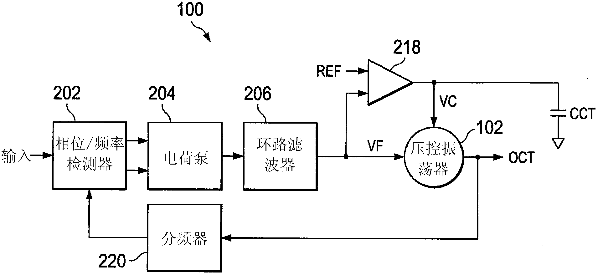
[0023] In general, PFD 202 , charge pump 204 , loop filter 206 , VCO 208 , and frequency divider 220 operate as a high bandwidth loop to generate output signal OUT from an input signal, similar to the high bandwidth loop of PLL 100 . PFD 202 compares the feedback signal from frequency divider 220 with input signal IN to generate rising and falling signals for char...


PUM


Abstract

A phase locked loop (PLL 200), such as employed in a synthesizer, has two continuous (analog) control loops and one digital on-off ('bang-bang') control loop. The control loop of PLL 200 provides additional discrete time controls for a voltage controlled oscillator (VCO 208). The control loop measures the coarse voltage (VC) and input signal (IN) to adjust the switched capacitor array (214) to help decrease settling time. Precision lock detector (222) monitors input phase error, while narrow window circuit (226) and wide window circuit (228) specify a voltage window. Based on lock detection from the precision lock detector (222) and a voltage window from the narrow and wide window circuits (226, 228), a window adjust circuit 224 sets threshold voltages VH, VL for the on-off (bang-bang) controller 230.

Description

technical field [0001] The present invention relates generally to phase locked loops (PLLs) and more particularly to improvements in PLL feedback control. Background technique [0002] Phase-locked loops (PLLs) are commonly used in synthesizer subsystems. An example of a conventional PLL 100 using continuous calibration is shown in FIG. 1 . PLL 100 is generally composed of phase / frequency detector (PFD) 202, charge pump 204, loop filter 206, dual gain voltage controlled oscillator (VCO) 102, frequency divider 220, amplifier 218, and calibration capacitor CCT. In this configuration, there are two separate analog loops, a low bandwidth loop (formed with error amplifier 218 and VCO 102) and a high bandwidth loop (formed with frequency divider 220 and VCO 102), making the low bandwidth The loop can apply a coarse tuning voltage VC to the VCO 102 and the high bandwidth loop can apply a fine tuning voltage VF to the VCO 102 . [0003] In operation, the high bandwidth loop opera...

Claims


Application Information

Patent Timeline
IPC IPC(8): H03L7/099
CPCH03L2207/06H03L7/103H03L7/099
Inventor 凯文·G·费森
Owner TEXAS INSTR INC
Why Eureka
Try Eureka