
Catalytic cracking fume desulfuration wastewater treatment process

A desulfurization wastewater, catalytic cracking technology, applied in water/sewage multi-stage treatment, water/sludge/sewage treatment, chemical instruments and methods, etc., can solve the problems of low impact capacity, high effluent COD, long residence time, etc. , to achieve the effect of strong impact resistance, stable water quality and simple operation

Active Publication Date: 2012-12-12
CHINA PETROLEUM & CHEM CORP +3
View PDF10 Cites 51 Cited by
  • Summary
  • Abstract
  • Description
  • Claims
  • Application Information

AI Technical Summary

Problems solved by technology

[0003] There are many shortcomings in the existing process: relying on sedimentation and other technologies in the process of solid-liquid separation, the suspended matter in the effluent cannot meet the standard, and the residence time is long, and the floor area is large; the oxidation of sulfite to sulfate is not complete, resulting in high COD in the effluent ; After solid-liquid separation, the investment in sludge treatment is large; the impact capacity is small; in addition, the equipment occupies a large area, it is difficult to repair and maintain, the investment in supporting facilities is high, the operating procedures are cumbersome, the working environment is harsh, and it is intermittent production and easy to corrode , the oxidation is not complete, the water quality after separation and separation is poor, and the discharge cannot meet the standards, etc. Most of the treatment processes are intermittent and cannot be operated continuously

Method used


Image

  • Catalytic cracking fume desulfuration wastewater treatment process
  • Catalytic cracking fume desulfuration wastewater treatment process

Examples


Embodiment Construction

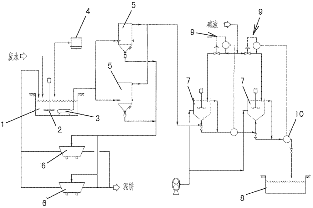
[0013] Such as figure 1 As shown, the desulfurization waste slurry, that is, the wastewater after catalytic cracking flue gas desulfurization, enters the slurry pool 1, mixes with the flocculant from the flocculant tank 4, and stirs in the slurry pool 1 with the mixer 2 to mix the wastewater and the flocculant evenly. The mixed waste water enters the expanded tube filter 5 by means of the delivery pump 3 (two sets are arranged side by side in the figure), and a coagulation reaction occurs at the lower end of the expanded tube filter 5, flocculating the tiny particles to form a large The flocs are then filtered through the filter membrane of the expanded tube filter 5 to achieve solid-liquid separation.

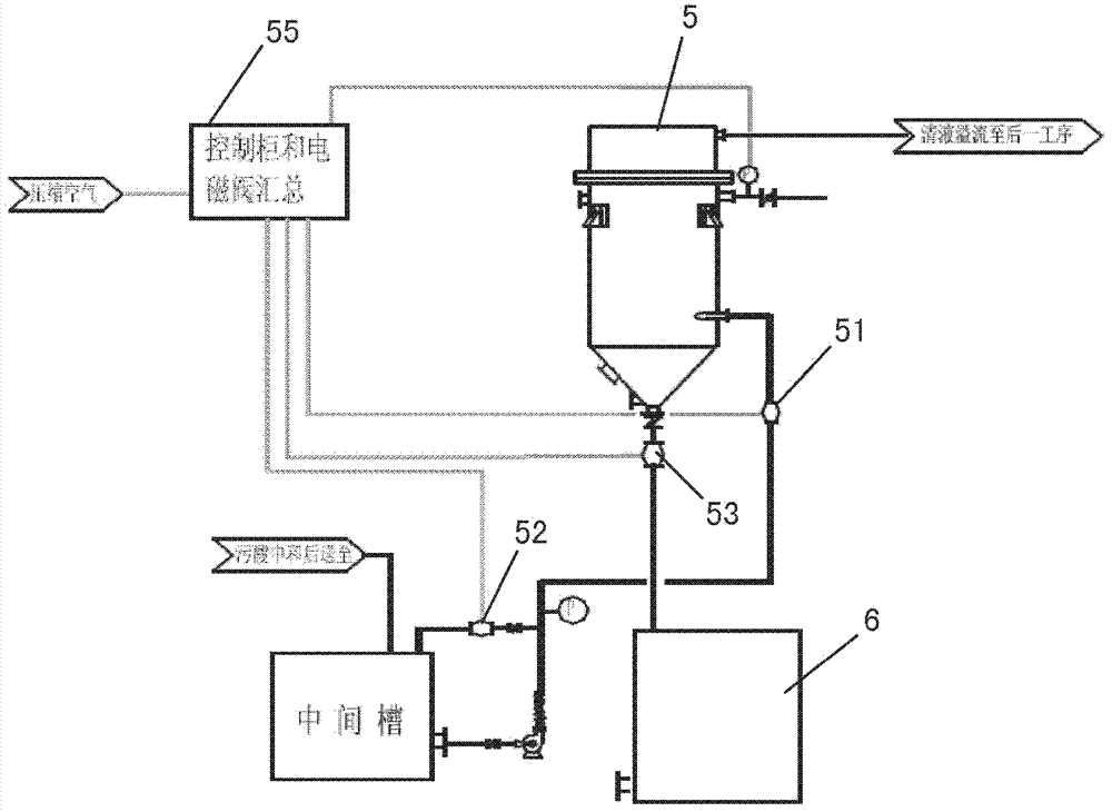
[0014] The bulging tubular filter 5 is a bulging tubular filter (for detailed composition, please refer to Chinese utility model patent CN200320104591.4, announcement number CN2650851), which is similar to the Gore membrane filter and mainly consists of a cylindrical shell, a ...


PUM


Abstract

A catalytic cracking fume desulfuration wastewater treatment process is characterized in that wastewater is discharged to a slurry pool and is mixed with a flocculating agent, a stirrer is used for stirring the wastewater and the flocculating agent, the wastewater and the flocculating agent are mixed evenly, the wastewater after being mixed is discharged to an expansion tube type filter and is subjected to the coagulation reaction at the lower end of the expansion tube type filter, small particulate matters in the wastewater are flocculated, large flocculating bodies are formed, the solid-liquid separation is achieved through the filtration of a filtering film, thick slag and supernatant fluid are obtained, the supernatant fluid is discharged to an oxidation tank further, the thick slag is subjected to back washing and enters a subsequent filtering box, the thick slag is concentrated and dewatered in the filtering box, mud cakes which are concentrated are transported outwards, the water of dehydration returns to the slurry pool again, is mixed with the wastewater and is processed again, the false chemical oxygen demand (COD) which contains sulfite and bisulfite is oxidized and removed by the supernatant fluid in the oxidation tank, and the sewage which meets standards is discharged. Compared with the prior art, the process has the advantages that the area occupied by devices is small, the operation cost is low, the solid and the liquid can be separated completely, the working environment of workers is good, device parameters can be set in accordance with parameters of different materials, and the application is wide.

Description

technical field [0001] The invention relates to a process for treating waste water from catalytic cracking flue gas desulfurization. Background technique [0002] During normal operation of the catalytic cracking flue gas dedusting and desulfurization system, the content of suspended solids, chloride ions, and dissolved solids in the circulating absorption liquid needs to be controlled. If the above indicators exceed the standard, the circulation system needs to discharge part of the absorption liquid to ensure The efficiency of desulfurization, the absorption liquid is controlled by the regulating valve to discharge part of the slurry out of the system to meet the requirements of the desulfurization process. The main pollutants contained in waste slurry are suspended solids, supersaturated sulfite, sulfate and heavy metals. If these pollutants are not treated in time and discharged directly, they will definitely cause serious pollution to the environment. The current proce...

Claims


Application Information

Patent Timeline
IPC IPC(8): C02F9/04
Inventor 陈昕仝明严奇伟梁亮亢万忠周洪义王家骐王宏伟
Owner CHINA PETROLEUM & CHEM CORP
Learn More