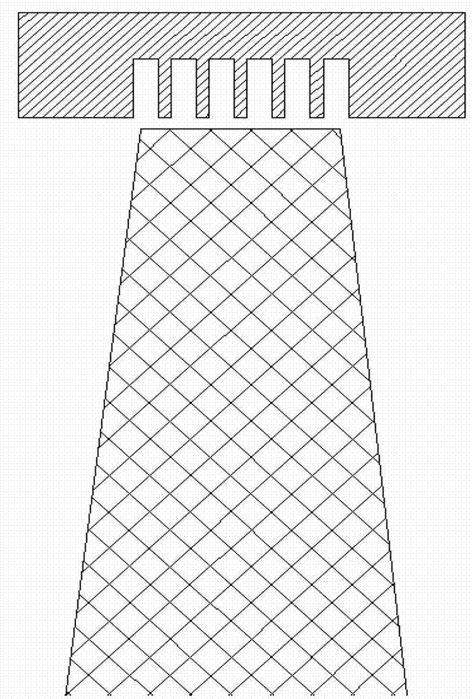
Ladder-shaped gap structure for gas compressor of aircraft engine
A technology of aero-engine and clearance structure, which is applied in the direction of machine/engine, liquid fuel engine, mechanical equipment, etc., can solve the problems of stability margin loss compressor efficiency, etc., to improve the stable working margin, facilitate processing, and simple layout. Effect
- Summary
- Abstract
- Description
- Claims
- Application Information
AI Technical Summary
Problems solved by technology
Method used
Image
Examples
Embodiment 1
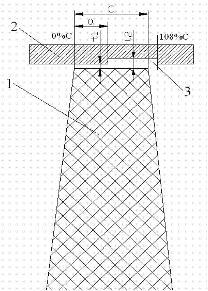
[0018] Embodiment 1: as figure 2 As shown, the aero-engine compressor described in this embodiment includes a rotor blade 1 and a casing shell 2, and the inner side wall of the casing casing 2 is provided with a stepped groove 3 with a small depth.
[0019] In order to improve the performance of the compressor and realize the organization and regulation of the complex flow in the tip area of the compressor rotor blade, a stepped groove 3 with a depth equal to the blade tip gap is set on the compressor case shell 2, aiming at the design of the compressor Pursue different goals to determine the size of the blade tip clearance and the slotting position of the stepped groove, and design different stepped clearance structures on the rotor blade tip. If higher pressure ratio and efficiency are pursued in the design, the rotor blade tip clearance t1 shall be set as 0.3% of the axial chord length of the rotor blade tip, and the depth shall be introduced within the range of 60% to 1...
PUM
 Abstract
Description
Claims
Application Information
 - R&D
- Intellectual Property
- Life Sciences
- Materials
- Tech Scout
- Unparalleled Data Quality
- Higher Quality Content
- 60% Fewer Hallucinations
Browse by: Latest US Patents, China's latest patents, Technical Efficacy Thesaurus, Application Domain, Technology Topic, Popular Technical Reports.
© 2025 PatSnap. All rights reserved.Legal|Privacy policy|Modern Slavery Act Transparency Statement|Sitemap|About US| Contact US: help@patsnap.com


