
Light-emitting lamp body heat dissipation structure, corresponding lighting device and manufacturing method thereof
A technology of heat dissipation structure and lamp body, which is applied to lighting devices, components of lighting devices, cooling/heating devices of lighting devices, etc. Fast, simple and practical structure, efficient heat dissipation
- Summary
- Abstract
- Description
- Claims
- Application Information
AI Technical Summary
Problems solved by technology
Method used
Image

Examples
Embodiment Construction
[0068] In order to understand the technical content of the present invention more clearly, the following examples are given in detail.
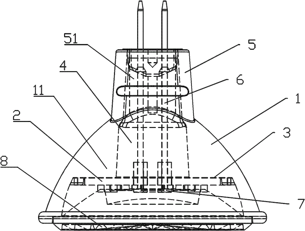
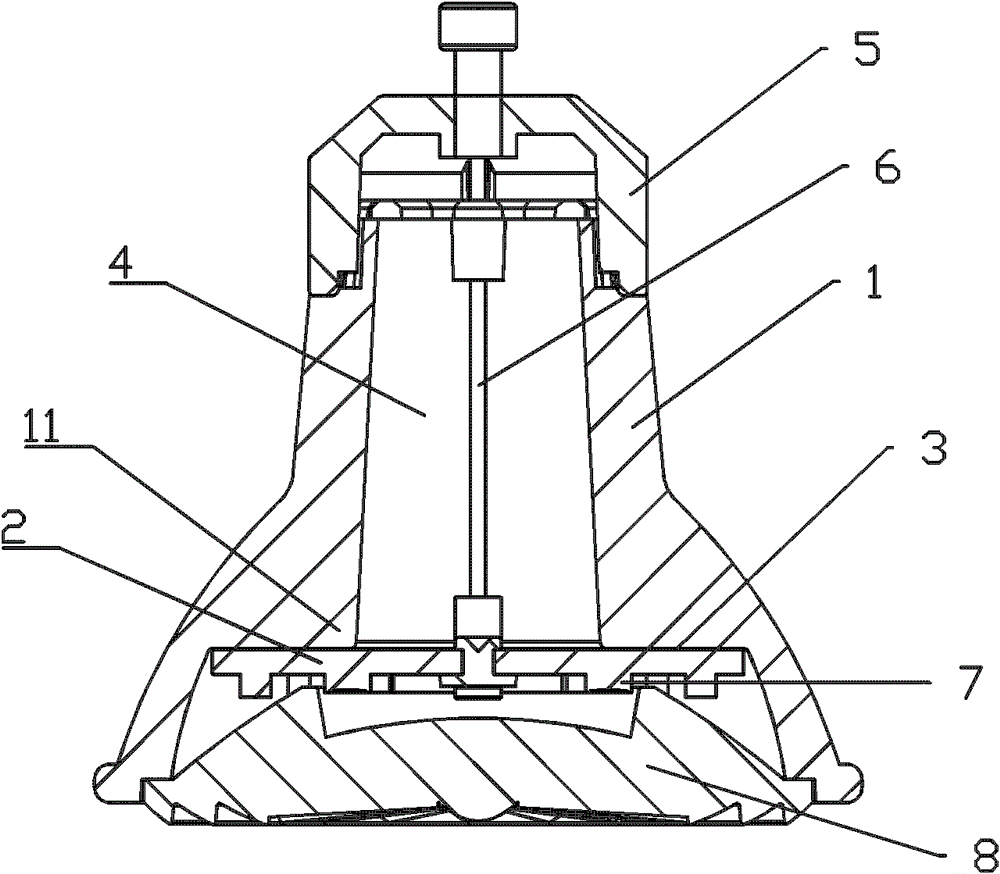
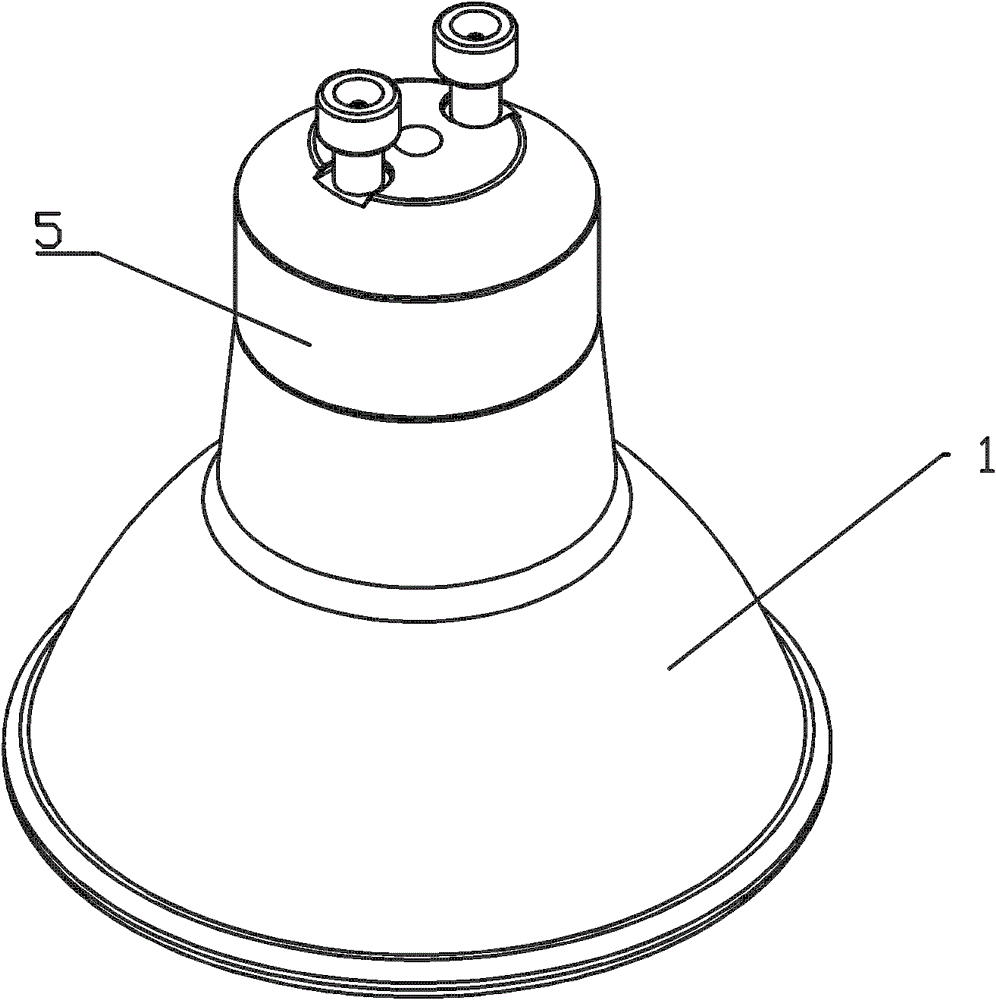
[0069] see Figure 1a , 1b As shown, the heat dissipation structure of the luminescent lamp body includes:
[0070] (1) glass housing 1;
[0071] (2) The heating component 2 arranged in the glass housing 1;
[0072] Wherein, the heat-generating component 2 is in close contact with the glass casing 1, and the area of the part in close contact is maximized.
[0073] Wherein, there is a heat transfer contact portion 11 on the inner wall of the glass housing 1, and the heat transfer contact portion 11 is in close contact with the heat-generating component 2; the heat transfer contact portion 11 can be at least in the following two forms:
[0074] (a) see Figure 2a As shown, it is an annular boss, and the bottom surface of the annular boss is in close contact with the heating component 2; this structure is easy to manufacture, and is more d...
PUM
 Abstract
Description
Claims
Application Information