
Laser projection system

A projection system and laser technology, applied in lighting devices, optics, instruments, etc., can solve the problems of large volume and the use of three-color laser beams, and achieve the effects of high color reproducibility, simple structure, and simple structure

Inactive Publication Date: 2012-12-12
ASIA OPTICAL CO INC
View PDF6 Cites 1 Cited by
  • Summary
  • Abstract
  • Description
  • Claims
  • Application Information

AI Technical Summary

Problems solved by technology

[0004] The technical problem to be solved by the present invention is to provide a laser projection system whose laser module only uses a single-wavelength laser A light source that simplifies laser projection systems, reducing size and cost

Method used


Image

  • Laser projection system

Examples


Embodiment Construction

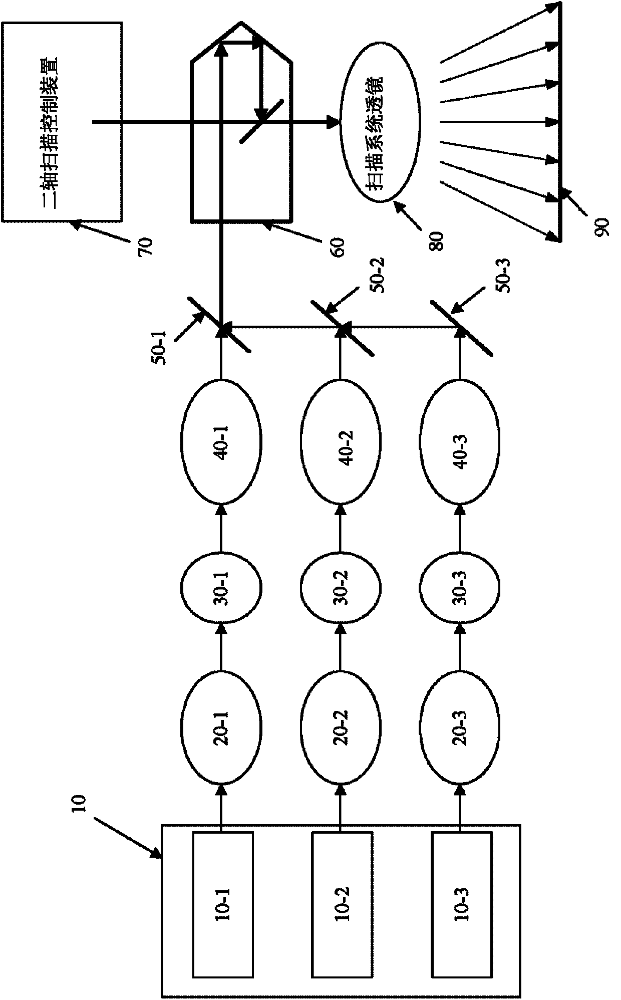
[0008] Please refer to figure 1 , represents the functional schematic diagram of the laser projection system of the present invention. The laser projection system of the present invention includes a laser module 10, a collimating lens 20-1, a collimating lens 20-2, a collimating lens 20-3, a red phosphor 30-1, a green phosphor 30-2, a blue phosphor Body 30-3, first collimating lens 40-1, second collimating lens 40-2, third collimating lens 40-3, first lens 50-1, second lens 50-2, third lens 50 -3. The prism 60 , the two-axis scanning control device 70 and the scanning system lens 80 .

[0009] The laser module 10 includes a single-wavelength laser light source 10-1, a single-wavelength laser light source 10-2, and a single-wavelength laser light source 10-3, corresponding to the red phosphor 30-1, the green phosphor 30-2, and the blue phosphor The bodies 30-3 respectively generate desired laser beams. The laser projection system of the present invention further includes thr...


PUM


Abstract

The invention relates to a laser projection system which comprises a laser module, a red phosphor, a green phosphor, a blue phosphor, a first collimating lens, a second collimating lens, a third collimating lens, a prism and a scanning system lens. The laser module is provided with at least one single wavelength laser light source serving as the light source. The red phosphor, the green phosphor and the blue phosphor are respectively excited by the first wavelength laser light source to emit red light, green light and blue light. The first collimating lens, the second collimating lens and the third collimating lens are respectively arranged on radiating paths of the red light, the green light and the blue light and are respectively used for changing the red light, the green light and the blue light to a red light parallel light beam, a green light parallel light beam and a blue light parallel light beam. The prism refracts the red light parallel light beam, the green light parallel light beam and the blue light parallel light beam. The scanning system lens projects the red light parallel light beam, the green light parallel light beam and the blue light parallel light beam which are refracted by the prism to an aiming plane to form imaging pictures.

Description

technical field [0001] The present invention relates to a laser projection system, in particular to a laser projection system using a single-wavelength laser light source. Background technique [0002] Existing projection devices mostly adopt halogen or electric arc bulb light sources. Although this type of light source has the advantage of high luminance, it has many disadvantages, such as large power consumption, high operating temperature, short lamp life and high price, and the size and weight cannot be further reduced due to heat dissipation. In recent years, related industries have also begun to develop laser projection equipment using laser light as a light source. If a projector using a laser light source as a light source has a simple structure and high color reproducibility. In addition, because it does not require a considerable volume and weight of the heat dissipation module due to the heat dissipation problem of conventional projectors using halogen bulbs, th...

Claims


Application Information

Patent Timeline
Patent Type & Authority Applications(China)
IPC IPC(8): G03B21/20G02B27/18F21V13/00
Inventor 熊坚智
Owner ASIA OPTICAL CO INC
Learn More