
Helium-filled system for removing grains in gas

A particle removal technology, which is applied in the field of nuclear power plant safety and environmental protection, can solve the problems of low power of electrostatic precipitator, affecting the safety of the surrounding environment, and poor removal effect of fine particles, so as to achieve simple control, convenient implementation and protection of the public Health and Environmental Effects

Inactive Publication Date: 2012-12-12
NORTH CHINA ELECTRIC POWER UNIV (BAODING)
View PDF8 Cites 9 Cited by
  • Summary
  • Abstract
  • Description
  • Claims
  • Application Information

AI Technical Summary

Problems solved by technology

Even the fourth-generation supercritical water reactors have special problems in the movement of particles due to the characteristics of supercritical water, which affects the safety of the surrounding environment
The generation of graphite dust in high-temperature gas-cooled reactors will also cause a series of problems, and may affect the safety and normal operation of the reactor
In the generation IV sodium-cooled fast reactor, the migration of accidental sodium particles will also endanger the safety of the system and the safety of people around it
At present, the removal of particulate matter in nuclear power plants mainly includes French-made sand pile filters, Swedish pebble filters, and German Venturi tube water filters. These measures have a better filtering effect on larger debris produced by severe nuclear power plant accidents , but the removal effect of fine particles is not good
The problem of fine particle removal is also a problem in the energy industry. Except for the better effect of electrostatic precipitators, there are no effective measures to form products
However, electrostatic precipitators cannot be widely used in nuclear power plants due to their low power and other issues.

Method used


Image

  • Helium-filled system for removing grains in gas
  • Helium-filled system for removing grains in gas
  • Helium-filled system for removing grains in gas

Examples


Embodiment Construction

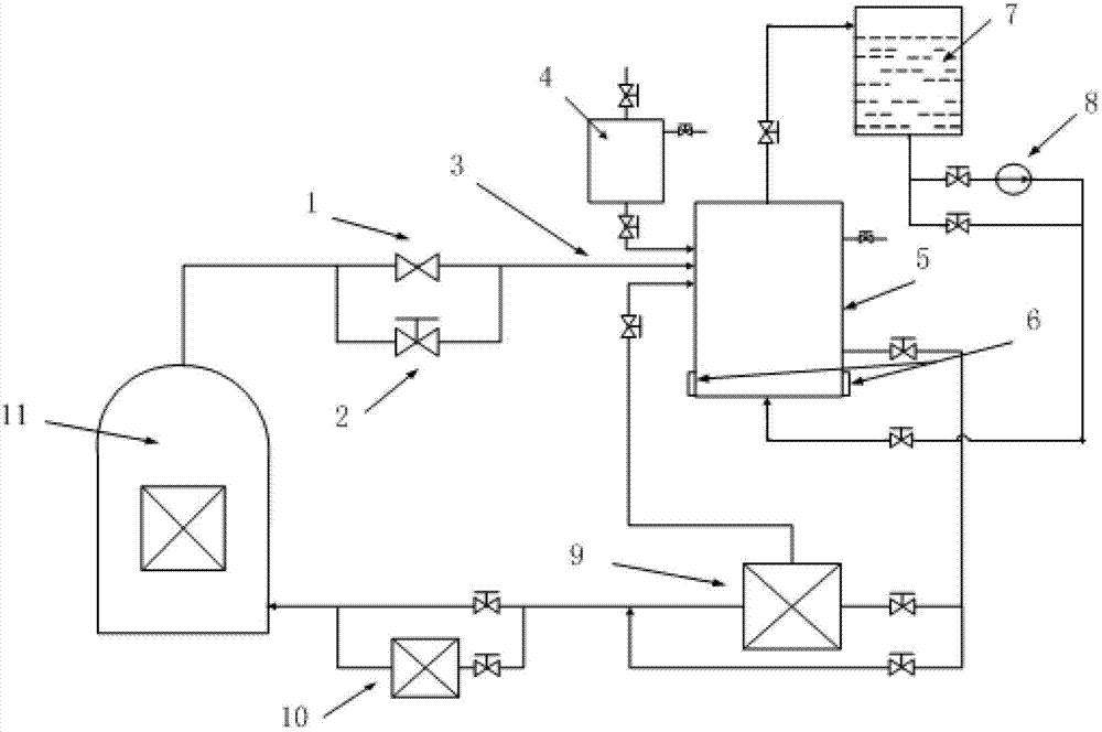
[0024] The present invention provides a helium-filled gas particle removal system. The present invention will be further described below in conjunction with the accompanying drawings and specific embodiments.

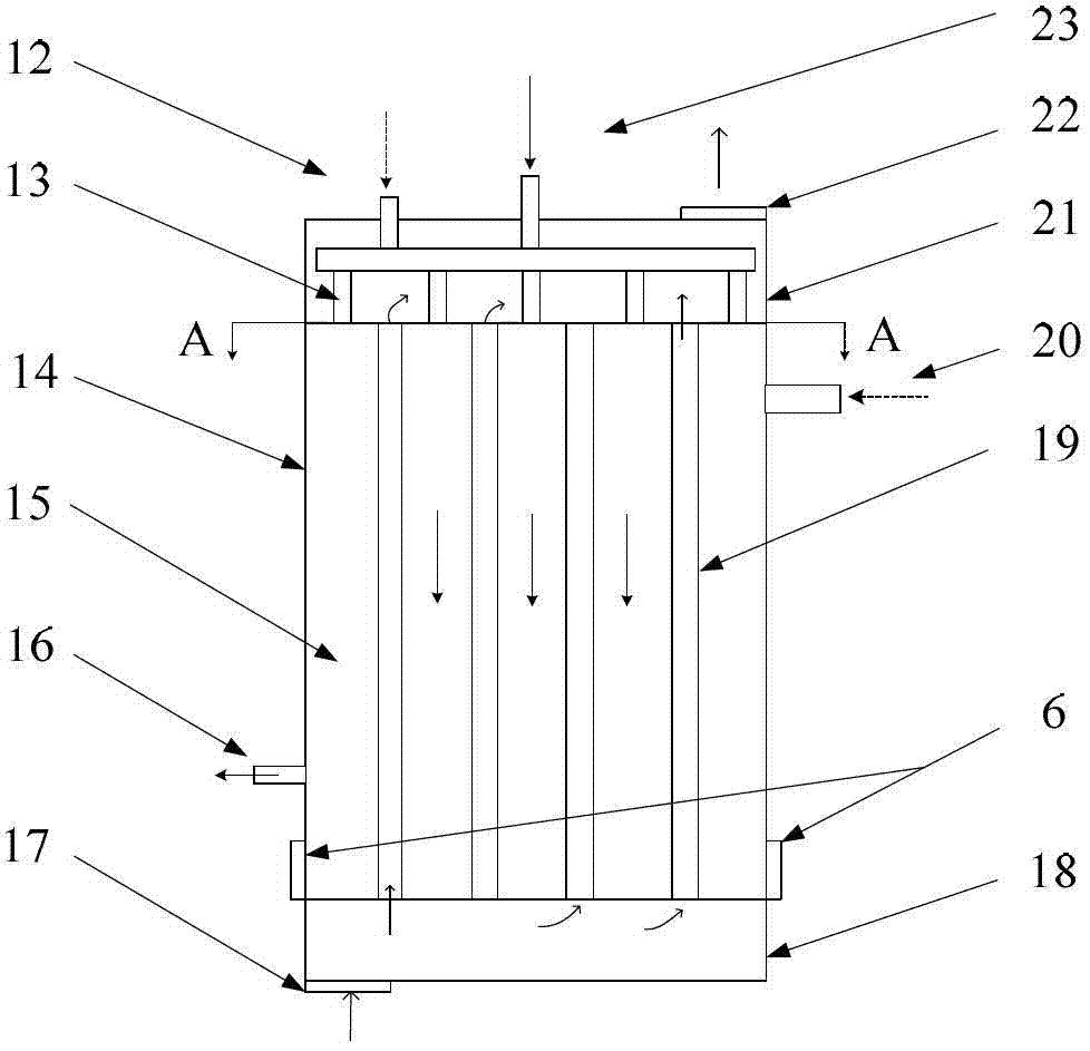
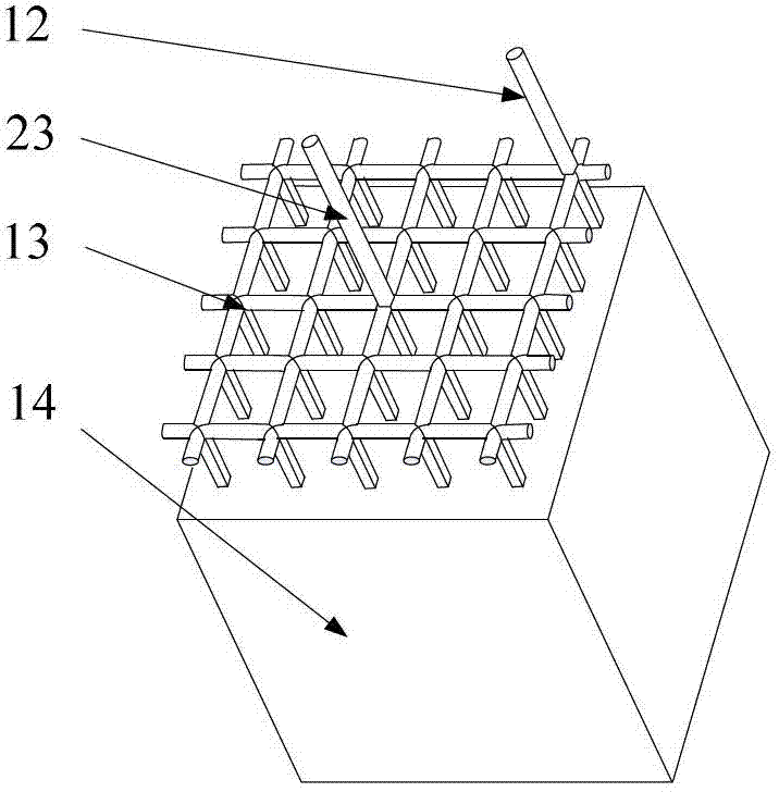
[0025] The core part of the system is the helium tank 5, and its structure is as follows figure 2 As shown: the helium tank 5 is divided into three parts from top to bottom: the upper header 21, the helium tank body 14 and the lower header 18; a number of staggered particle removal channels 15 are arranged in the helium tank body 14 and water cooling channel 19 (as Figure 4 ), the upper part of the side wall of the helium tank box body 14 is provided with a helium gas filling port 20, and the lower part is provided with an exhaust port 16; a grid-shaped intake pipe 13 is provided in the upper header 21, and the intake pipe 13 has two inlets and several outlets, the two inlets are respectively the air inlet 23 at the center and the helium gas return port 12 at the edg...


PUM


Abstract

The invention discloses a helium-filled system for removing grains in gas and belongs to the technical field of safety and environmental protection of a nuclear power plant. When a serious accident happens in the nuclear power plant, the inner pressure of a safety shell is increased, a connecting valve is opened and grains are conveyed to a helium box through a pipeline; the helium box is a pressure-bearing stainless steel box with a water-cooling wall; due to thermophoresis and turbulence effects, the grains are deposited in the helium box; and meanwhile, a helium containing box is cooled by a water pipe of an external device, so as to form a temperature field with a certain gradient in the helium containing box; and helium has a higher heat conductance, so that the thermophoresis deposition is higher in efficiency. A removing device is mounted on the exterior of the safety shell of the nuclear power plant, the implementation is convenient and the control is simple, so that the safe, efficient and reliable running of the nuclear power plant is ensured.

Description

technical field [0001] The invention belongs to the technical field of nuclear power plant safety and environmental protection, and in particular relates to a helium-filled gas particle removal system. Background technique [0002] In today's energy shortage in the world, nuclear power is the only energy that can achieve continuous power supply except for fossil energy. After the third nuclear power plant accident in Fukushima, Japan in 2011, the Chinese government established the basic policy of "safe and efficient" development of nuclear power. Therefore, it is a very important task to develop and develop effective measures to deal with severe nuclear power accidents. [0003] Radioactive particulate matter produced during severe accidents at nuclear power plants is of greatest concern. As we all know, even non-radioactive particles are extremely harmful to humans, PM 10 , PM 2.5 Such fine particulate matter has become an important problem that the international commun...

Claims


Application Information

Patent Timeline
IPC IPC(8): G21F9/02B01D45/00
Inventor 周涛陈娟樊昱楠汝小龙刘亮林达平王泽雷
Owner NORTH CHINA ELECTRIC POWER UNIV (BAODING)
Learn More