Improved method and apparatus for forming corrugated board

An equipment and corrugated technology, applied in the field of improved models and equipment for forming corrugated sheets, can solve problems such as damage to corrugated sheet corrugations and reduction of board strength

Inactive Publication Date: 2012-12-12
CORCEL IP LTD
View PDF6 Cites 11 Cited by
  • Summary
  • Abstract
  • Description
  • Claims
  • Application Information

AI Technical Summary

Problems solved by technology

[0029] Therefore, flexographic rubber printing is usually applied in volume, but since these require applying pressure to apply the ink to the substrate bonded to the corrugated sheet, this damages the corrugation of the corrugated sheet
This reduces the board's strength (i.e., structural integrity) as the corrugation becomes slightly collapsed due to flexo rubber printing
Also, the ink rollers can only produce low quality print on the plate - as can be seen on many apple or other fruit boxes

Method used


Image

  • Improved method and apparatus for forming corrugated board
  • Improved method and apparatus for forming corrugated board
  • Improved method and apparatus for forming corrugated board

Examples


Embodiment 1

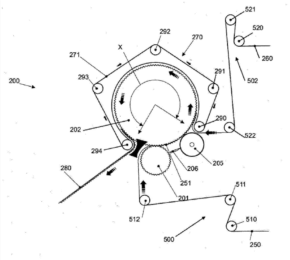
[0317] In order to calculate the productivity of the 1.6m diameter second fluted (ie, large) roller, in which the endless belt extends 76% around the second roller, the new formula RP=DHT / BT of the present invention is applied, which gives 0.76(π1. 6) / 0.05 RP (productivity), equal to 76m / min productivity, where 0.05 minutes is 3 seconds bonding time. This productivity is significantly lower than the productivity calculated by the applicant in WO2009 / 000085.

Embodiment 2

[0319] If the manufacturer needs a productivity of 143m / min and uses a glue with a BT of 0.033333 minutes (ie 2s), the new formula DHT of the present invention can be applied to express the diameter of the second flute (ie larger) roller as 0.93 x(π2r), and the diameter can be calculated by DHT=RP.BT, it will be (143×0.033333). Then, in order to obtain the diameter, the equation 0.93x(π2r)=(143×0.033333) is reorganized, so that 2r (that is, the diameter)=((143×0.033333) / 0.76) / π, which is equal to the diameter of 2m.

Embodiment 3

[0321] If you want to calculate the productivity of a 2m diameter roller, where BT is 0.05 minutes (ie, 3s). Apply the formula RP=DHT / BT 0.93(π2) / 0.05, which is equal to 116m / min.

[0322] In practice, the diameter of 2m is at or close to the limit that a pair of intermeshing fluted rollers can produce corrugated cardboard: as described in this article and in figure 2 Or as described in the applicant’s previous PCT application WO2009 / 145642. The reason why it is impossible in practice to have a large fluted roller with a diameter significantly greater than 2m (for example, a roller with a diameter of 2.5m, 3m or larger) is that the increased weight of such a roller makes it difficult to lift and move , Especially when it comes to the manufacture, maintenance and repair of such large rollers. Furthermore, rollers with a diameter greater than 2 m are heavier and require significantly more energy to rotate the rollers, and therefore increase production costs. Moreover, maintainin...


PUM

PropertyMeasurementUnit
diameteraaaaaaaaaa
diameteraaaaaaaaaa

Abstract

The present invention relates to an apparatus for, and method of, bonding a substantially planar porous sheet material to a porous corrugated sheet material in a continuous process, the apparatus comprising a linear corrugator module (300) comprising a corrugating roller (306); an endless fluted conveyor belt (301) wherein the fluted surface (302) of the conveyor belt intermeshes with the teeth on the corrugating roller; a glue applicator (308); and an endless tensioned belt assembly which holds the planar and corrugated sheets together so a bond is formed between them. The production rate (and therefore the dimensions of the corrugating roll) is governed by the formula RP=DHT/BT, wherein RP is the rate of production in metres/minute; DHT is the distance in metres for which the respective sheets are held together; and BT is the bond time of the adhesive in minutes.

Description

Technical field [0001] The present invention relates to an improved method and apparatus for forming corrugated boards. Specifically, the present invention discloses a method and equipment for manufacturing single-sided corrugated board and / or double-sided corrugated board in some embodiments. Background technique [0002] For ease of reference only, the present invention will now be described in connection with the production of single-sided cardboard, which of course should not be considered as a limitation, as certain embodiments of the present invention can be used to make double-sided corrugated boards. [0003] As used throughout this specification, the terms ripple and corrugation and their grammatical variants are used interchangeably and refer to a series of alternating ridges (peaks) and valleys (troughs). [0004] Single-sided corrugated paperboard is well known and widely used in industry, especially in the packaging industry where it is used as a protective filler and p...

Claims


Application Information

Patent Timeline
Patent Type & Authority Applications(China)
IPC IPC(8): B31F1/28B32B29/08
CPCB31F1/2818B32B29/005B32B7/12B32B29/08B32B2250/26B31F1/2895B31F1/30B32B3/26B32B2255/12B32B2255/26
Inventor 帕特里克・彼得鲁斯・安东尼厄斯・玛丽亚・范贝洛
Owner CORCEL IP LTD
Why Eureka
Try Eureka