
Pipe bender precision control method

A technology of precision control and pipe bending machine, which is applied in the field of pipe bending machine control, can solve the problems of uncontrollable bending precision of pipe bending machine, many times of manual bending, and high scrap rate, so as to improve competitiveness, reduce labor intensity, and reduce scrap products Effect

Active Publication Date: 2012-12-19
WISCODRI WUGANG ENG
View PDF10 Cites 6 Cited by
  • Summary
  • Abstract
  • Description
  • Claims
  • Application Information

AI Technical Summary

Problems solved by technology

[0006] The technical problem to be solved by the present invention is to solve the problems that the bending precision of the pipe bending machine cannot be controlled during the process of bending pipe fittings, the number of manual bending times is high, the strength is high, and the scrap rate is high, and a method for controlling the precision of the pipe bending machine is provided.

Method used

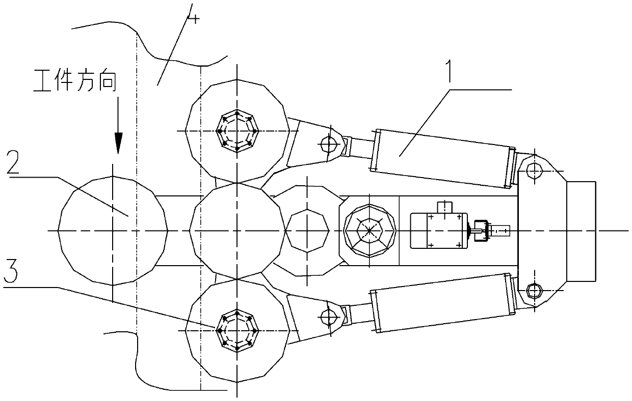
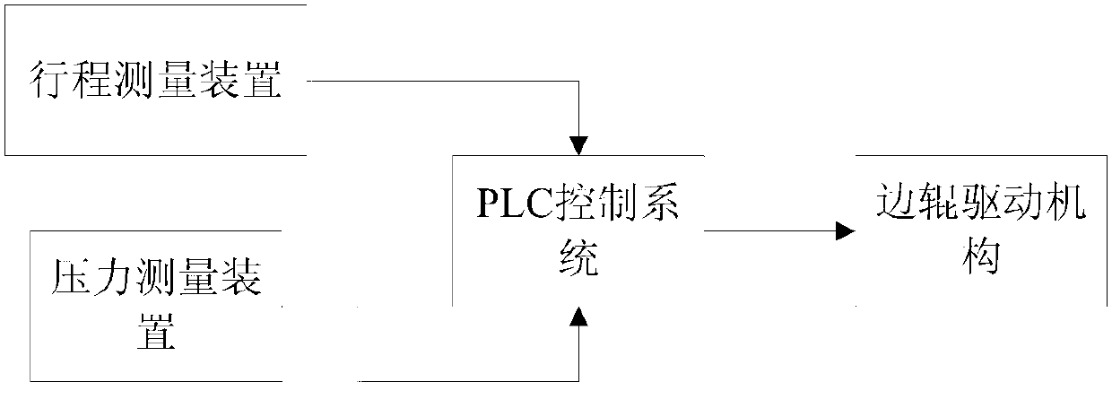

Image

  • Pipe bender precision control method
  • Pipe bender precision control method
  • Pipe bender precision control method

Examples


Embodiment 1

[0039] Bending the straight pipe of stainless steel seamless steel pipe into a U-shaped pipe, taking the synchronous and symmetrical movement of the rollers on both sides as an example, the main control process is as follows:

[0040] (1) Input the pipe size parameters and steel material type, the PLC control system collects the material parameters of the corresponding steel grades stored in the system according to the input results, calculates and displays the pipe bending moment M of different pipe materials at the corresponding curvature radius by the moment formula; In this embodiment, the pipe material is a stainless steel seamless steel pipe material;

[0041] bending moment The formula takes an equal sign, where,

[0042] D - the outer diameter of the pipe;

[0043] ρ—the radius of curvature of the curved neutral layer;

[0044] σ b - the tensile strength of the material;

[0045] W——flexural section modulus;

[0046] Input pipe size parameters: pipe outer diamet...

Embodiment 2

[0058] Bending the straight pipe of stainless steel seamless steel pipe into a U-shaped pipe, taking the asymmetrical movement of the rollers on both sides as an example, the main control process is as follows:

[0059] (1) Input pipe size parameters: pipe outer diameter D is 10-16mm, wall thickness is 0.5-1.5mm;

[0060] Collect and store the material parameters of the steel grades: the radius of curvature ρ of the curved neutral layer is 32mm; the tensile strength of the stainless steel seamless steel pipe material σ b is 381~600Mpa, in this embodiment σ b The value is 600Mpa;

[0061] Calculate the bending moment M=443N.m;

[0062] (2) The detected distance L between each side roller and the main roller at the beginning 0 is 300mm; at this time, because there is no bending pressure, the hydraulic thrust F driven by the side roller is 0;

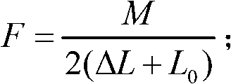
[0063] (3) The PLC system is based on the constraint relationship between the bending moment M, the bending pressure F and the moving...


PUM

PropertyMeasurementUnit
Outer diameteraaaaaaaaaa
Wall thicknessaaaaaaaaaa
Tensile strengthaaaaaaaaaa

Abstract

The invention relates to a pipe bender precision control method. Because travel control switches for a left side roll and a right side roll, a bending pressure sensor, a PLC (programmable logic controller) control system and a display are added, the relative position coordinates and bending pressure data of the side rolls and a main roll in work are transmitted to the PLC control system, the PLC control system works out and then transmits the bending radius and radian of a workpiece to the display, and thereby pipe bending precision control is enhanced. The pipe bender precision control method can accurately work out the bending radius, reduce the labor of repeated pipe bending as the result of inaccurate artificial pipe radius prediction in pipe bending, save the pipe-bending time, increase the working efficiency of workers and decrease labor intensity.

Description

technical field [0001] The invention relates to a control method for a pipe bending machine, which is applicable to industries such as petroleum, chemical industry, hydropower, shipbuilding, steel structure and machinery manufacturing. Background technique [0002] The pipe bending machine is specially used for the bending and forming of pipes, which can be rolled into circular, arc, spiral and other pipe fittings. It is widely used in various industries such as petroleum, chemical industry, hydropower, shipbuilding, steel structure and machinery manufacturing. [0003] When the pipe bending machine is working: the pipe is first clamped by the main roller and the left and right rollers. On the one hand, the left and right rollers rotate through the hydraulic system through the motor and gear. Under the action of the roller, it moves linearly. On the other hand, under the action of the oil cylinder, the left and right rollers do arc swing around the central axis, so as to pro...

Claims


Application Information

Patent Timeline
IPC IPC(8): B21D7/12B21D7/08
Inventor 吴光行戴江波
Owner WISCODRI WUGANG ENG
Learn More