In-groove type helical milling method

A processing method and groove feature technology, applied in the processing field of mechanical parts, can solve the problems of low efficiency, manual grinding, and difficulty in ensuring accuracy, and achieve the effects of fast processing speed, improved quality and stable load

Active Publication Date: 2012-12-19
SUZHOU MACHINING PRECISION ELECTRONICS
View PDF6 Cites 31 Cited by
  • Summary
  • Abstract
  • Description
  • Claims
  • Application Information

AI Technical Summary

Problems solved by technology

[0009] The purpose of the present invention is to invent a helical milling process with fast processing speed and high efficiency for the inner profile of the slo...

Method used


Image

  • In-groove type helical milling method
  • In-groove type helical milling method
  • In-groove type helical milling method

Examples


Embodiment Construction

[0039] The present invention will be further described below in conjunction with the accompanying drawings and embodiments.

[0040] Such as Figure 1-6 shown.

[0041] A method for helical milling of groove feature inner profile, which comprises the following steps:

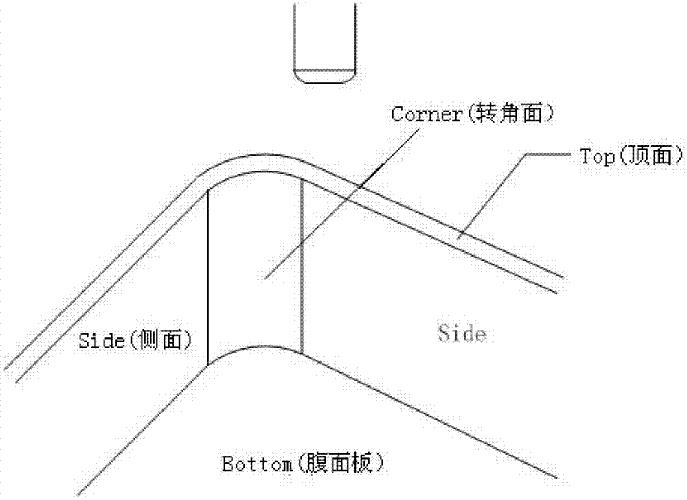
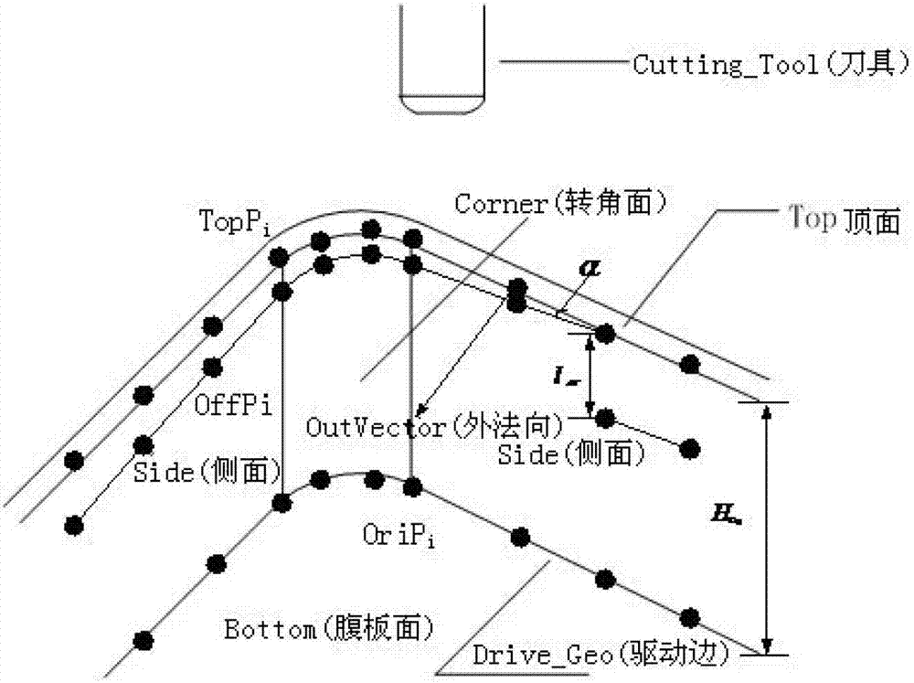
[0042] Step 1. Input the groove feature internal shape part into the CAM software system to preprocess the part. The input of the part feature information is to read the feature information list of the part, or to obtain the drive related to the internal shape by manually clicking on the feature of the part Geometry, and then extract the internal tool path to generate the driving line according to the driving geometry; the relevant driving geometry of the spiral tool path milling internal shape includes corner surfaces, side surfaces, top surfaces, and web surfaces, and discretize the driving lines to form the underlying discrete points;

[0043] Step 2, offset the bottom discrete point to the top surface of t...


PUM


Abstract

The invention discloses an in-groove type helical milling method. The in-groove type helical milling method comprises the following steps of 1, extracting an in-groove type drive wire, dispersing the drive wire into base discrete points, axially offsetting the base discrete points to a top surface of a groove along a cutter so that top discrete points are formed, selecting a cutting feed point, setting an arc-shape cutting feed mode, and carrying out axial and reverse offsetting along the cutter based on the top discrete points according to a helical angle and an axial cutting depth so that a first layer of the discrete points are formed and a first layer of cutter location points are formed further, 2, axially, reversely and orderly offsetting the first layer of cutter location points layer by layer to a penultimate layer along the cutter according to the axial cutting depth so that a middle layer of cutter location points are formed, and 3, setting a helical angle of a last layer of cutter location points to zero degree so that the last layer of cutter location points are formed, setting an arc-shape cutter retracting mode, setting a cutter-axis vector of each one of the cutter location points, and connecting the all cutter location points to obtain an integral milling track of in-groove type helical milling. The in-groove type helical milling method can reduce frequency of cutter retracting, improve cutting stability and improve surface processing quality and processing efficiency.

Description

technical field [0001] The invention relates to a processing method of mechanical parts, in particular to a milling processing method of internal groove parts, in particular to a processing method of helically milling the characteristic internal shape of grooves by using a numerical control milling machine. Background technique [0002] Slot features are widely used in aircraft structural parts. At present, the commonly used processing method is to adopt the axial priority processing method. The tool rails processed by this method are processed at the same height for each layer, and each layer needs to be advanced and retracted once. Using this method for processing requires frequent tool advance and retreat, and the processing efficiency is low. Every time the tool advances and retreats, tool marks will be formed on the surface of the part, and the cutting force will change frequently, making the machining process unstable. [0003] The helical CNC tool trajectory helps to ...

Claims


Application Information

Patent Timeline
IPC IPC(8): B23C3/28
Inventor 李迎光刘长青王伟刘旭郝小忠周鑫
Owner SUZHOU MACHINING PRECISION ELECTRONICS
Why Eureka
Try Eureka