Lifting jack oiling machine

A fuel dispenser and jack technology, applied in bottle filling, liquid filling, packaging, etc., can solve the problems of low generalization, achieve the effects of reducing labor intensity, saving labor resources, and protecting the environment

Inactive Publication Date: 2012-12-19
CHANGSHU TONGRUN AUTO ACCESSORY
View PDF10 Cites 5 Cited by
  • Summary
  • Abstract
  • Description
  • Claims
  • Application Information

AI Technical Summary

Problems solved by technology

At present, workers usually inject hydraulic oil into the oil storage chamber by injection. This operation method has the following shortcomings: First, because there is air in the oil storage chamber, it is necessary to drive the air out of the oil storage chamber while filling the hydraulic oil. , so the oil filling speed is often relatively slow, which affects the operation efficiency; second, due to manual oil filling, the labor intensity of workers is high; third, a lot of manpower is invested, which wastes labor resources; The phenomenon is serious, which causes waste on the one hand and affects the environment on the job site on the other hand
[0003] In order to solve the above problems, the applicant has carried out a literature search, however, the reason is not found in the published patents and non-patent literature to eliminate the above technical problems The enlightenment that can be used for reference is because the tooling equipment has the characteristics of special equipment that meets specific process requirements during the manufacture of a certain product and / or subsequent processes, and usually needs to meet the non-interference and positioning of the workpiece during the work process Waiting for request
And because the tooling equipment has the exclusive characteristics of functioning for a certain product, so the degree of generalization is extremely low, and it is often designed and manufactured by the manufacturer of the product itself.

Method used


Image

  • Lifting jack oiling machine

Examples


Embodiment Construction

[0014] In order to enable the examiners of the patent office, especially the public, to understand the technical essence and beneficial effects of the present invention more clearly, the applicant will describe in detail the following in the form of examples, but none of the descriptions to the examples is an explanation of the solutions of the present invention. Any equivalent transformation made according to the concept of the present invention which is merely formal but not substantive shall be regarded as the scope of the technical solution of the present invention.

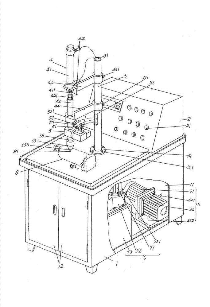
[0015] please see figure 1 , a base 1 whose shape and size are not limited by the illustration but is preferably shown in the figure is given. The base 1 has a base cavity 11 and is also pivotally arranged on one side of the base 1 The access door 12 is used for the maintenance (overhaul and maintenance) of the vacuum pumping mechanism 6 and the oil filling mechanism 7 which are arranged in the base cavi...


PUM


Abstract

The invention relates to a lifting jack oiling machine, which belongs to the tooling apparatus technical field. The lifting jack oiling machine comprises a base which has a base chamber at the bottom, an electrical control case which is arranged at the top of the base and positioned at one side of the top, a column possessing a column chamber which is fixed at the top of the base, a reversing valve elevating system which is connected on the column, a reversing valve which is connected to the reversing valve elevating system, a vacuum-pumping mechanism which is arranged in the base chamber and is connected to the reversing valve elevating system and a reversing valve air path, an oil filling mechanism which is arranged in the base chamber and is connected to a reversing valve oil path; and the electrical control case is connected to the reversing valve, the vacuum-pumping mechanism and the oil filling mechanism in an electrical control mode. The lifting jack oiling machine has the advantages that the work efficiency is enhanced, the labor intensity of workers can be mitigated, the labor force resource can be saved, no bubbling and drop-leaking phenomena can not generated during the work process, and the work on-site environment can be guaranteed.

Description

technical field [0001] The invention belongs to the technical field of tooling equipment, and in particular relates to a jack oiler, which is used for injecting hydraulic oil into a jack oil storage cavity. Background technique [0002] As known in the industry, during the production process of the hydraulic jack, specifically, in the follow-up process after the assembly is completed, hydraulic oil needs to be poured into the oil storage chamber between the oil cylinder and the jacket. At present, workers usually inject hydraulic oil into the oil storage chamber by injection. This operation method has the following shortcomings: First, because there is air in the oil storage chamber, it is necessary to drive the air out of the oil storage chamber while filling the hydraulic oil. , so the oil filling speed is often relatively slow, which affects the operation efficiency; second, due to manual oil filling, the labor intensity of workers is high; third, a lot of manpower is inv...

Claims


Application Information

Patent Timeline
Patent Type & Authority Applications(China)
IPC IPC(8): B67C3/04B67C3/22B67C3/26
Inventor 钱军
Owner CHANGSHU TONGRUN AUTO ACCESSORY
Why Eureka
Try Eureka