Heavy oil catalytic cracking feeding atomizing nozzle

A heavy oil catalytic and atomizing nozzle technology, which is applied in catalytic cracking, cracking, petroleum industry, etc., can solve the problems of high feed oil injection speed, mutual influence of inlet area, and wear of steam injection holes, so as to suppress ejection backflow and eliminate Large-diameter droplets and anti-coking effect

Active Publication Date: 2014-12-24
LUOYANG SENDE PETROCHEM ENG
View PDF14 Cites 0 Cited by
  • Summary
  • Abstract
  • Description
  • Claims
  • Application Information

AI Technical Summary

Problems solved by technology

[0004] However, in the actual use process, the above-mentioned nozzles have more or less the following problems: first, the atomization effect of the feedstock oil needs to be further improved; Coking phenomenon occurs; the third is that the injection speed of the atomized raw material oil droplets sprayed out by the nozzle is too high, which seriously breaks the catalyst; the fourth is that the atomized steam and the raw material oil interact with each other in the inlet area of ​​the nozzle, and even appear when the fog When the pressure of steam (or raw oil) fluctuates, the raw oil (or atomized steam) cannot be introduced into the nozzle
[0007] Through research, it is found that the shortcomings of 200410010045.3 mainly lie in two aspects: one is that there is still an accumulation of oil film on the inner wall of the local area inside the nozzle, that is, the atomization effect of 200410010045.3 can still be further improved
In addition, 200410010045.3 nozzle position steam injection hole setting makes it more "sensitive" to the change of operating parameters, because 200410010045.3 steam injection hole is connected with the secondary steam chamber, when the steam pressure, flow rate fluctuates, and even the raw material oil flow rate fluctuates Any time, it may cause the catalyst to suck back, and even cause the wear of the steam injection hole

Method used


Image

  • Heavy oil catalytic cracking feeding atomizing nozzle
  • Heavy oil catalytic cracking feeding atomizing nozzle
  • Heavy oil catalytic cracking feeding atomizing nozzle

Examples


Embodiment Construction

[0036] The present invention is described in conjunction with accompanying drawing and specific embodiment;

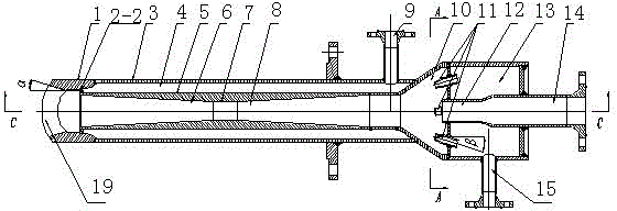
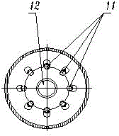
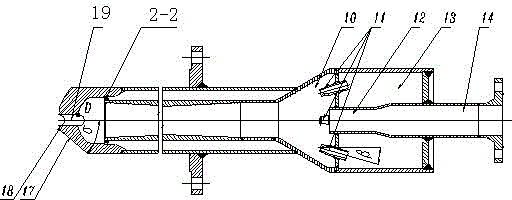
[0037] Such as figure 1 shown, and refer to figure 2 , image 3 , Figure 4 , a feed atomizing nozzle for catalytic cracking of heavy oil, the nozzle includes an inner pipe 5, an outer pipe 3, a nozzle 1, a raw oil inlet 14 and a primary steam inlet 15; the ring between the inner pipe 5 and the outer pipe 3 The cavity forms an annular secondary steam chamber 4 and is provided with a secondary steam inlet 9; the inner pipe 5 has a constriction section 6, a throat section 7 and a diffusion section 8, and the front end of the nozzle 1 has a nozzle outlet 19; the raw material The oil inlet 14 communicates with the manifold chamber 13, and communicates with the frustum-shaped mixing chamber 10 through the raw oil nozzle 12; the primary steam nozzle 11 communicates with the primary steam inlet 15, and the primary steam nozzle 11 is a ring A plurality of surrounding stoc...


PUM


Abstract

The invention belongs to the technical field of petroleum refining and provides a heavy oil catalytic cracking feeding atomizing nozzle. The heavy oil catalytic cracking feeding atomizing nozzle comprises an inner tube (5), an outer tube (3), a shower nozzle (1), a raw material oil inlet (14) and a primary steam inlet (15), a plurality of primary steam nozzles (11) surrounding a raw oil nozzles (12) are communicated with the primary steam inlet (15), the first stage pulverization is carried out on part of raw oil in a mixing chamber (10),, and other part of the raw oil enters the inner tube (5) to conduct the second stage pulverization. A secondary steam spraying hole I (2-2) conducts the third stage pulverization on the raw oil. The heavy oil catalytic cracking feeding atomizing nozzle solves the problem that oil film aggregation exists on an inner wall of a partial position inside the nozzle, removes major-diameter liquid drops, obtains atomization grain sizes required by a catalytic cracking process, and avoids coking of the raw oil on the inner wall of a riser reactor above the nozzle.

Description

technical field [0001] The invention belongs to the technical field of petroleum refining, and mainly relates to a heavy oil catalytic cracking feed atomizing nozzle. Background technique [0002] Raw oil feeding atomization nozzle is an important equipment of catalytic cracking unit in the field of petroleum refining. In the tube reactor, it mixes and reacts with the catalyst in the riser reactor. [0003] In recent years, the feed oil atomization nozzles used in catalytic cracking units mainly include throat type LPC type (90209410.6), KH type with supersonic atomizing steam double throat type (89207961.9, 200420066089.3), BWJ type with swirl structure (98233035.9,), UPC-ɑ type with porous steam distributor (00109776.8), and CCK type with secondary atomization structure (99219391.5); foreign similar technologies mainly include S&W The company's target nozzle, the multi-nozzle Optimix nozzle with a built-in porous steam distributor developed by UOP, the ATOMAX nozzle with...

Claims


Application Information

Patent Timeline
Patent Type & Authority Patents(China)
IPC IPC(8): C10G11/00B05B7/04
Inventor 范怡平吴朝能陈维许煜许栋五
Owner LUOYANG SENDE PETROCHEM ENG
Why Eureka
Try Eureka