MEMS (Micro Electro Mechanical System) scanning type laser heterodyne interferometer and method thereof in measuring glass stress

A laser heterodyne interference and scanning technology, which is applied in the direction of measuring, measuring devices, instruments, etc. by measuring the change of optical properties of materials when they are stressed, can solve the problems of difficult control and low detection accuracy, and achieve easy control Effect

Inactive Publication Date: 2012-12-19
HARBIN INST OF TECH
View PDF4 Cites 15 Cited by
  • Summary
  • Abstract
  • Description
  • Claims
  • Application Information

AI Technical Summary

Problems solved by technology

[0008] (3) In the process of measuring the stress distribution of optical materials, the detection of elliptical light has been carried out by artificially or mechanically rotating the polarizer, which is difficult to control and the detection accuracy is not high.

Method used


Image

  • MEMS (Micro Electro Mechanical System) scanning type laser heterodyne interferometer and method thereof in measuring glass stress
  • MEMS (Micro Electro Mechanical System) scanning type laser heterodyne interferometer and method thereof in measuring glass stress
  • MEMS (Micro Electro Mechanical System) scanning type laser heterodyne interferometer and method thereof in measuring glass stress

Examples


specific Embodiment approach 1

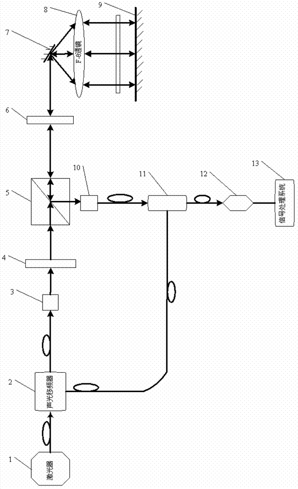
[0047] Specific implementation mode one: combine figure 1 Describe this embodiment, the MEMS scanning type laser heterodyne interferometer described in this embodiment, it comprises laser 1, acousto-optic frequency shifter 2, the first fiber coupler 3, λ / 2 wave plate 4, polarization beam splitting prism 5. λ / 4 wave plate 6, MEMS vibrating mirror 7, F-θ lens 8, mirror 9, second fiber coupler 10, fiber combiner 11, detector 12 and signal processing system 13;

[0048] The light beam emitted by the laser 1 is incident on the acousto-optic frequency shifter 2, and the emitted light after passing through the acousto-optic frequency shifter 2 is the 1st-order light of frequency f and the 0-order light of frequency f', and the 0-order light of frequency f' is incident to the first fiber coupler 3,

[0049] The light beam coupled by the first fiber coupler 3 is incident on the λ / 2 wave plate 4, the light beam transmitted by the λ / 2 wave plate 4 is incident on the polarization beam sp...

specific Embodiment approach 2

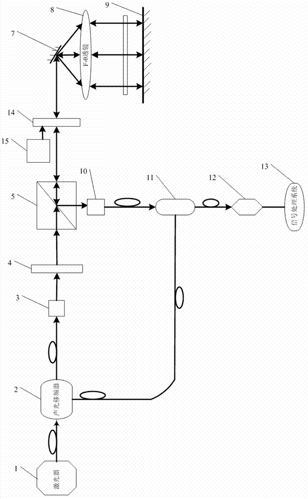
[0051] Specific implementation mode two: combination figure 2 Describe this embodiment mode, this embodiment mode also provides a kind of MEMS scanning type laser heterodyne interferometer, it comprises laser device 1, acousto-optic frequency shifter 2, first fiber coupler 3, λ / 2 wave plate 4, polarization beam splitter Prism 5, MEMS vibrating mirror 7, F-θ lens 8, reflector 9, second fiber coupler 10, fiber beam combiner 11, detector 12, signal processing system 13, Kerr effect crystal 14 and electrode drive circuit 15 ;

[0052] The light beam emitted by the laser 1 is incident on the acousto-optic frequency shifter 2, and the emitted light after passing through the acousto-optic frequency shifter 2 is the 1st-order light of frequency f and the 0-order light of frequency f', and the 0-order light of frequency f' is incident to the first fiber coupler 3,

[0053] The light beam coupled by the first fiber coupler 3 is incident on the λ / 2 wave plate 4, the light beam transmi...

specific Embodiment approach 3

[0056] Specific embodiment three: this embodiment is a further description of the MEMS scanning laser heterodyne interferometer described in specific embodiment two, the driving signal period of the electrode drive circuit 15 is the same as the period scanned by the MEMS vibrating mirror 7, and the electrode driving A half cycle delay is set within the cycle of the driving signal of the circuit 15 .


PUM


Abstract

The invention relates to an MEMS (Micro Electro Mechanical System) scanning type laser heterodyne interferometer and a method thereof in measuring glass stress, relating to an interferometer and a method thereof in measuring the glass stress and aiming at solving the problem of limitation of the measurement of the glass stress on infrared materials. Light emitted by a laser passes through an acoustooptic frequency shifter to become 1-grade light with the frequency of f and 0-grade light with the frequency of f', the 1-grade light is signal light, the 0-grade light is local oscillating light, the 1-grade light passes through a lambda / 2 wave plate to enter a polarization beam splitter prism and then transmitted through a part, scans a sample through an MEMS vibrating mirror 7 and then reflected by a reflecting mirror to return according to an original optical path; light beams pass through the part again and then reflected into horizontal components by the polarization beam splitter prism, carry out frequency beat with the 0-grade light and respectively form the angles of 0 degree and 45 degrees with the polarization direction of incident light through a changed part; a signal processing system processes two currents detected by a detector to obtain the glass stress of the sample; and the part is a lambda / 4 wave plate or a Kerr effect crystal adding an electrode in a direction at 45 degrees. The MEMS scanning type laser heterodyne interferometer disclosed by the invention is used for measuring the glass stress.

Description

technical field [0001] The invention relates to an interferometer and a method for measuring glass stress, in particular to a MEMS scanning laser heterodyne interferometer and a method for measuring glass stress. Background technique [0002] When there is stress in the optical material, the surface of the processed optical element will slowly deform over time, seriously affecting the imaging quality and greatly reducing the life of the optical element. Inhomogeneous stress distribution can also cause a decrease in the quality of optical uniformity, making the refractive index distribution inconsistent. These will deform the wavefront passing through the optical element and deteriorate the image quality. Therefore, the magnitude of stress is one of the important indicators of the optical properties of optical materials. In the process of processing high-precision optical elements such as corner cube prisms, right-angle prisms, and pentagonal prisms, if you choose optical ma...

Claims


Application Information

Patent Timeline
Patent Type & Authority Applications(China)
IPC IPC(8): G01L1/24G01N21/23
Inventor 王春晖庞亚军曲杨李小宝
Owner HARBIN INST OF TECH
Why Eureka
Try Eureka