Fretting-wear ultrasonic-vibration ultralong-life fatigue test apparatus

A technology of fretting friction and fatigue testing, which is applied in testing wear resistance, etc., can solve the problems of low experimental accuracy and difficult design, and achieve the effect of improving test accuracy

Active Publication Date: 2012-12-19
SICHUAN UNIV
View PDF5 Cites 20 Cited by
  • Summary
  • Abstract
  • Description
  • Claims
  • Application Information

AI Technical Summary

Problems solved by technology

[0005] The invention provides a fretting friction ultrasonic vibration ultra-long-life fatigue test device, which solves the problems of low experimental accuracy and relatively difficult design of the fretting friction super-long-life fatigue test device in the past

Method used


Image

  • Fretting-wear ultrasonic-vibration ultralong-life fatigue test apparatus
  • Fretting-wear ultrasonic-vibration ultralong-life fatigue test apparatus
  • Fretting-wear ultrasonic-vibration ultralong-life fatigue test apparatus

Examples


Embodiment 1

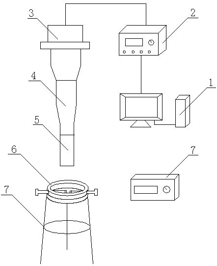
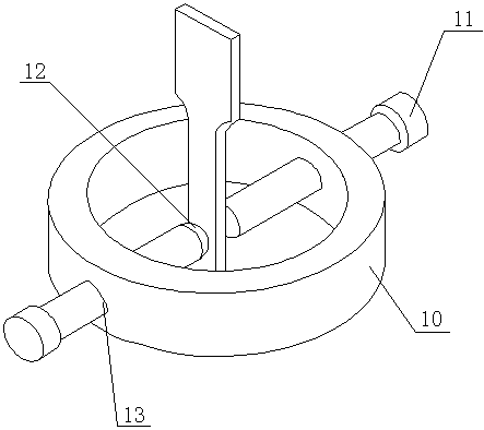
[0022] Such as figure 1 , figure 2 and Figure 4 As shown, the present invention includes an ultrasonic fatigue test device, a fretting friction device 6 and a temperature test device. The ultrasonic fatigue test device includes a computer system 1, an ultrasonic generator 2, a piezoelectric ceramic transducer 3 connected in sequence, and a piezoelectric ceramic transducer The lower end of the transducer 3 is fixedly connected with the horn 4, and the output end of the horn 4 is connected with a cylindrical extension rod 5 coaxial with the horn 4, and the cross section of the output end of the horn 4 is the same as that of the extension rod 5. The cross-sections are equal in size, and the temperature testing device includes a thermometer 8, which is used to measure the temperature of the friction section of the sample. A support device 7 is provided directly below the extension rod 5, and the support device 7 is a triangular support frame. The friction device 6 is fixed on ...

Embodiment 2

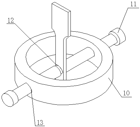
[0026] Such as figure 1 , image 3 and Figure 4 This embodiment is basically the same as Embodiment 1, except that the contact surface of the front end of the friction pressure head 12 is a plane.

[0027] The working principle of the present invention is: as Figure 5 As shown, first, under the control of the computer system 1, the ultrasonic generator 2 converts the 50Hz electrical signal into a 20KHz ultrasonic sine wave signal output, and then the piezoelectric ceramic transducer 3 converts the ultrasonic sine wave signal into a mechanical The vibration signal, the horn 4 amplifies the vibration displacement amplitude from the piezoelectric ceramic transducer 3 to the displacement amplitude required by the sample 9, and at the same time determines the position for installing the fretting friction device 6 according to the displacement amplitude to realize the fretting friction system . Among them, the fretting friction system adjusts the position of the fixed ring 10 ...


PUM


Abstract

The invention discloses a fretting-wear ultrasonic-vibration ultralong-life fatigue test apparatus. The apparatus comprises an ultrasonic fatigue test device, a fretting wear device (6) and a temperature test device, wherein the ultrasonic fatigue test device comprises a computer system (1), an ultrasonic generator (2) and a piezoelectric ceramic energy transducer (3) which are sequentially connected; the lower end of the piezoelectric ceramic energy transducer (3) is fixedly connected with a amplitude transformer (4); the output end of the amplitude transformer (4) is connected with a cylindrical extension rod (5) coaxial to the amplitude transformer (4); the size of the cross section of the output end of the amplitude transformer (4) is equal to the size of the cross section of the extension rod (5); and the temperature test device comprises a temperature test meter (8). By adopting the above structure, the apparatus has the advantages of experiment design difficulty reduction and high test precision.

Description

technical field [0001] The invention relates to a fatigue test device, in particular to a fretting friction ultrasonic vibration ultra-long life fatigue test device. Background technique [0002] Fretting fatigue refers to the micron-scale relative motion between the contact interfaces of closely fitting parts under fatigue load, which causes material wear or fatigue cracks. Fretting friction can cause wear on the surface of the contact surface, causing component occlusion, loosening, and increased noise; fretting friction can accelerate the initiation and expansion of fatigue cracks, greatly reducing the fatigue life of components. In the fields of aviation, railway and machinery, it is easy to cause machine parts failure or even catastrophic accidents due to fretting friction fatigue failure. Over the past two decades, with the development of medical technology, the problem of fretting friction fatigue has also appeared in medical fields such as bone grafting and dentistr...

Claims


Application Information

Patent Timeline
Patent Type & Authority Applications(China)
IPC IPC(8): G01N3/56
Inventor 王清远田仁慧刘永杰
Owner SICHUAN UNIV
Why Eureka
Try Eureka