Modularized multi-level converter with auxiliary diode

A modular multi-level, auxiliary diode technology, applied in the direction of converting AC power input to DC power output, electrical components, output power conversion devices, etc., can solve problems such as large amount of calculation, current loop oscillation, and affecting response speed , to simplify the measurement and control circuit, reduce the number, and control the simple effect

Inactive Publication Date: 2012-12-19
TSINGHUA UNIV
View PDF6 Cites 69 Cited by
  • Summary
  • Abstract
  • Description
  • Claims
  • Application Information

AI Technical Summary

Problems solved by technology

This method can be used not only for reactive power compensation equipment, but also for harmonic compensation equipment, but this method is also very dependent on the current of the valve body, and at the same time, it is necessary to calculate the switching occupation of the capacitor voltage of each unit in each switching cycle. Air ratio adjustment
When the converter is used as a medium-voltage power grid device, the number of valve body units is relatively large, and the calculation load of the voltage equalization control will be large, which will prolong the control cycle of the digital controller, and will significantly reduce the phase margin of the converter's current loop, affecting the response speed , and even cause the oscillation of the current loop
[0009] In the above-mentioned voltage equalization control method, it is necessary to set a voltage detection and control circuit in each unit, so that the complexity of the control circuit is relatively high
There are few research reports on how to simplify the detection and control of multilevel converter topology

Method used


Image

  • Modularized multi-level converter with auxiliary diode
  • Modularized multi-level converter with auxiliary diode
  • Modularized multi-level converter with auxiliary diode

Examples


Embodiment

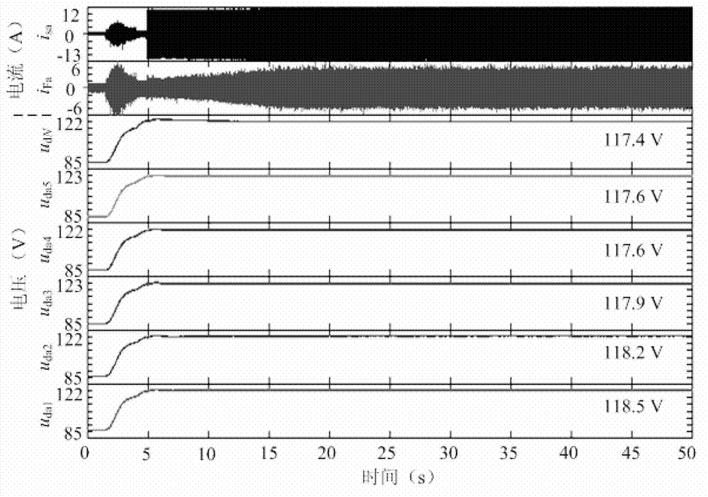
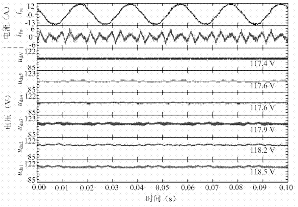
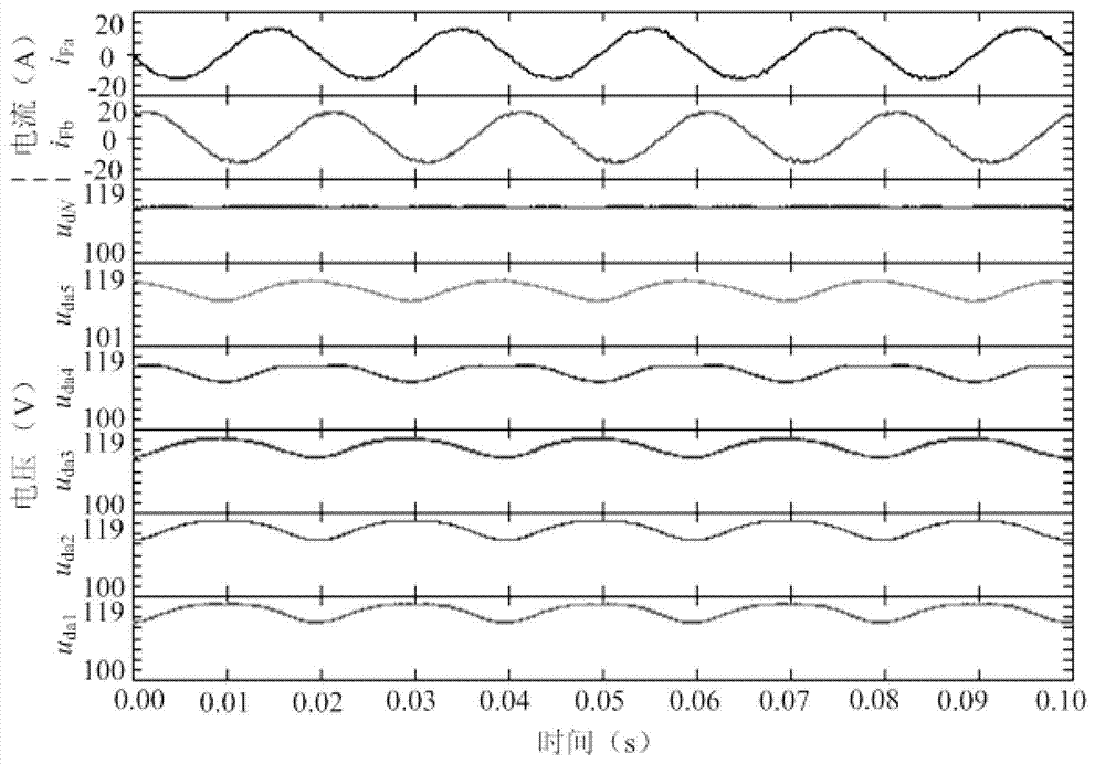
[0050] Embodiment: according to the principle of the present invention, a star-connected 7-level modular multilevel converter prototype with auxiliary diodes has been set up. When it works in the harmonic compensation state, the overall situation waveform of the experimental results can be obtained (such as Figure 7 , Figure 8 shown), in which, the order of the waveforms from top to bottom is: grid phase a current, phase a valve body current with auxiliary diode MMC, phase a valve body common unit capacitor voltage, a phase 5th stage unit capacitor voltage, a Phase 4 cell capacitor voltage, a phase 3 cell capacitor voltage, a phase 2 cell capacitor voltage, a phase 1 cell capacitor voltage. It can be seen from this that the voltage balance of capacitors at all levels in the steady-state valve body is good. When the prototype of the 7-level modular multilevel converter with auxiliary diodes works in the state of reactive power output (such as Figure 9 shown), the sequence ...


PUM


Abstract

The invention relates to a modularized multi-level converter with an auxiliary diode. The modularized multi-level converter comprises a three-phase valve body, and three active energy feedback circuits respectively connected to the three-phase valve body, wherein each phase of valve body comprises 2M half-bridge inversion units and 2M-1 auxiliary diodes; direct current capacitors of the 1-(2M-1)th serially connected half-bridge inversion units are respectively connected with one auxiliary diode, and the final (2M)th half-bridge inversion unit is serially connected to form the valve body; the 1-Mth half-bridge inversion units form the upper-half part of the valve body to output a negative polarity voltage; and the (M+1)th to 2Mth half-bridge inversion units form the lower-half part of the valve body to output a positive polarity voltage. The auxiliary diodes and the active energy feedback circuits form a capacitor voltage sharing loop, the modularized multi-level converter realizes capacitance self voltage sharing effect, and realizes that the unit capacitance voltage is measured by using less direct current voltage sensors, thus the detection and the control of multi-level topology are greatly simplified. The modularized multi-level converter can be used in occasions such as reaction compensation and harmonic treatment of a medium-voltage or high-voltage power grid.

Description

technical field [0001] The invention relates to a topology structure of a multilevel converter, in particular to a modular multilevel converter with auxiliary diodes used in occasions such as reactive power compensation and harmonic control of medium-voltage or high-voltage power grids. Background technique [0002] With the continuous development of power electronics technology, high voltage and large capacity have become an important development direction of power electronics technology, and high voltage and large capacity power electronic converters have been used more and more in high voltage and large capacity occasions. Applications such as: new HVDC and light HVDC, medium or high voltage static var generator (Static Var Generator, SVG), active filter (Active Power Filter, APF), high voltage frequency converter, and New power generation technologies: wind power generation, photovoltaic power generation, etc., and high-voltage, large-capacity power electronic converters...

Claims


Application Information

Patent Timeline
Patent Type & Authority Applications(China)
IPC IPC(8): H02M7/5387H02J3/18H02J3/01
CPCY02E40/26Y02E40/30Y02E40/20Y02E40/40
Inventor 姜新建高聪哲
Owner TSINGHUA UNIV
Why Eureka
Try Eureka