Composite body

A composite and integral technology, applied in the field of composites, can solve the problems of low bonding strength and achieve the effect of high bonding strength and high adhesion

Inactive Publication Date: 2012-12-19
TUNGALOY CORP
7 Cites 15 Cited by

AI-Extracted Technical Summary

Problems solved by technology

However, in these bonding methods, the intermediate layer made of metal foil is thick, and therefore, ...

Method used

[0033] Tools 1, 2 and 3 were used for interrupted machining of hardened steel. The machining conditions were cutting speed Vc=100m/min, cutting depth ap=0.5mm, and feed rate f=0.25mm/rev, and outer diameter turning was performed on a round bar inserted with two U-shaped grooves. As a result, when the cutting time reached 8 minutes, the brazing portion of the tool 3 was greatly chipped. On the other hand, the machinable cutting time of Tool 1 was 15 minutes, and when the cutting time reached 15 minutes, flaking occurred on the cBN sintered body. However, at the joint surface b...

Abstract

Disclosed is a composite body comprising a cBN sintered body and a hard alloy that are firmly bonded. The composite body comprises a cBN sintered body, a hard alloy, and a bonding layer between the cBN sintered body and the hard alloy, wherein the bonding layer is a metal 0.1-5[mu]m thick.

Application Domain

Technology Topic

Image

  • Composite body
  • Composite body
  • Composite body

Examples

  • Experimental program(2)

Example Embodiment

[0019] Example 1
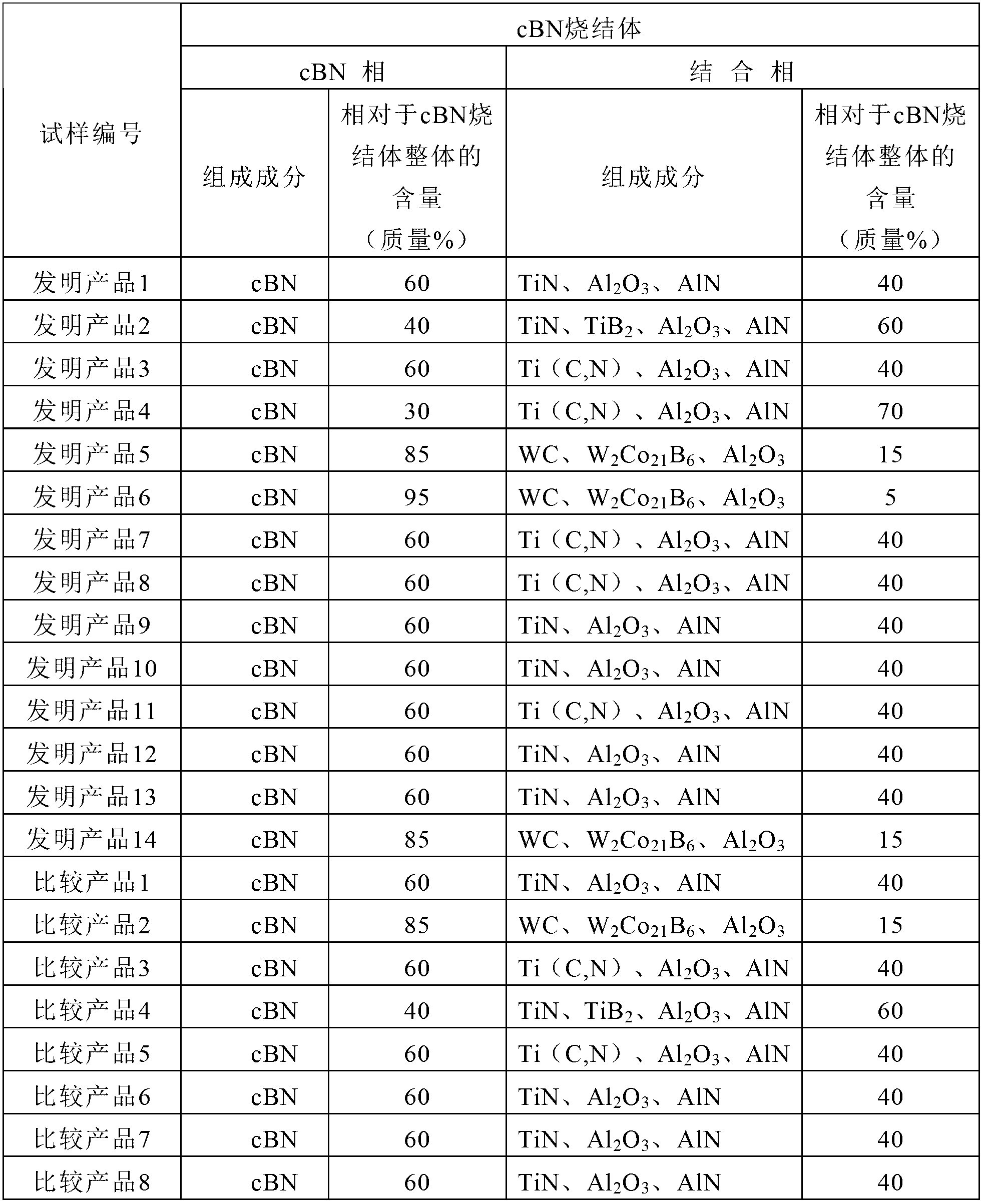
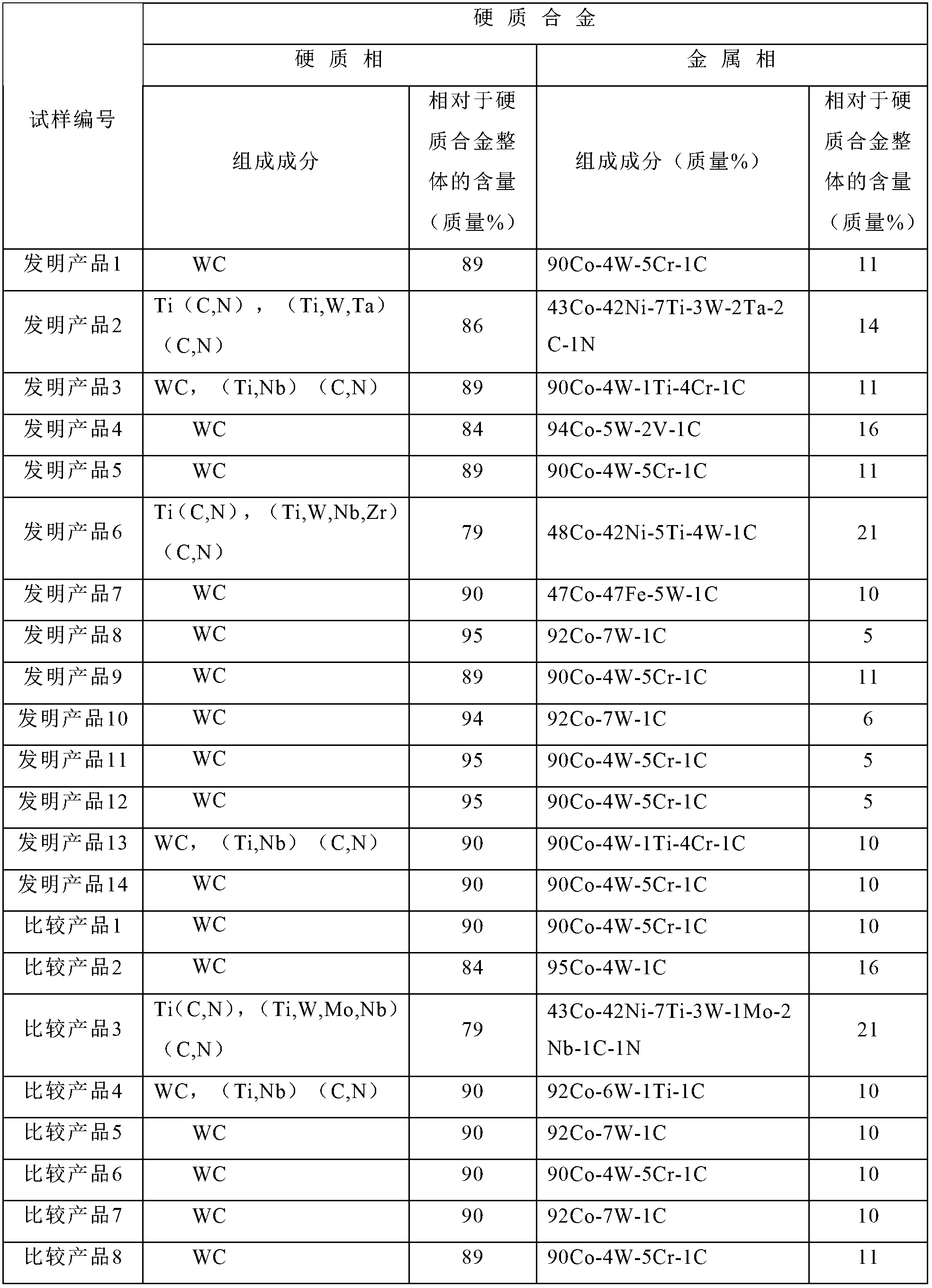
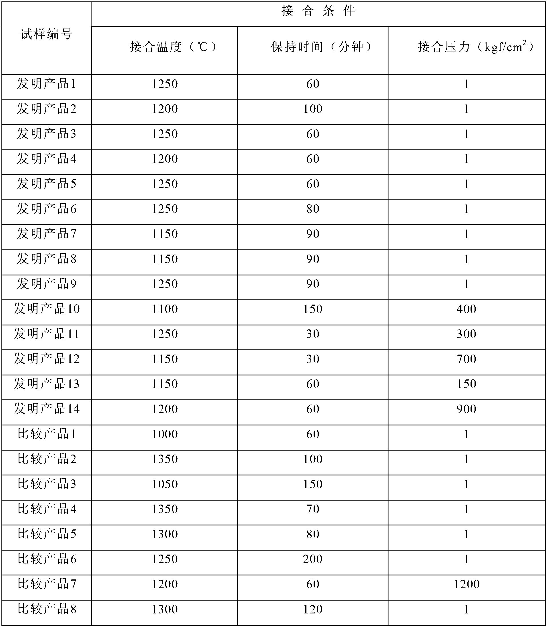
[0020] A disc-shaped cBN sintered body having the composition shown in Table 1 and having a diameter of 30 mm and a thickness of 1.5 mm, and a disc-shaped cemented carbide having a diameter of 30 mm and a thickness of 3.0 mm having the composition shown in Table 2 were prepared. Using diamond abrasive grains, etc., the joint surfaces of all samples were mirror-polished, and then placed in acetone for 10 minutes of ultrasonic cleaning. Then, using a hot pressing apparatus, the bonding surface of the cBN sintered body and the bonding surface of the cemented carbide were overlapped, and the load shown in Table 3 was applied, and the temperature was raised from room temperature to the bonding temperature shown in Table 3 in a vacuum. Then, after holding the bonding pressure, bonding temperature, and holding time shown in Table 3, cooling was performed. After cooling, the applied load was removed to obtain a composite body in which the cBN sintered body and the cemented carbide were joined.
[0021] Table 1
[0022]
[0023] Table 2
[0024]
[0025] table 3
[0026]
[0027] From the obtained composite, a test piece for component analysis of 10×10×4.5 mm and a shear test piece of 15×15×4.5 mm were cut by wire cutting. The thickness of the bonding layer was measured by scanning electron microscope (SEM), and the composition of the bonding layer was analyzed by X-ray energy dispersive spectrometer (EDS). In the shear test, a universal testing machine was used, the cemented carbide side was fixed, and a load was applied toward the vicinity of the interface on the cBN sintered body side from above to measure the shear strength. Table 4 shows the thickness, composition and shear strength of the bonding layer in each sample.
[0028] Table 4
[0029]
[0030] According to Table 4, it can be seen that the shear strength of the inventive product is high. Since the bonding temperature of Comparative Product 1 was low and the bonding layer was not sufficiently formed, bonding was basically not possible. The holding time of Comparative Product 2 was long, resulting in an excessively thick bonding layer and a decrease in shear strength. In addition, since the bonding was performed at a high temperature of 1350° C., the cBN phase in the cBN sintered body was converted into the hBN phase, resulting in a decrease in shear strength. The bonding layer of Comparative Product 3 was very thin, so that the compositional analysis of the bonding layer was not possible. The comparative product 3 was the same as the comparative product 1, but the bonding temperature was low and the bonding layer was not sufficiently formed, so that the bonding was basically not possible. The comparative product 4 is the same as the comparative product 2, but the thickness of the bonding layer is too thick and the shear strength decreases. Moreover, the Co content in the bonding layer of the comparative product 4 was small, the intensity|strength of the bonding layer itself decreased, and the shear strength was decreased. The comparative products 5 and 8 are the same as the comparative product 2, and their bonding temperature is high, so that the cBN phase is converted into hBN, and the shear strength is decreased. The bonding time of Comparative Product 6 was long, resulting in thickening of the thickness of the bonding layer and decrease in shear strength. The comparative product 7 had a high joining pressure, which caused plastic deformation of the cemented carbide during joining, so that the joining could not be performed.

Example Embodiment

[0031] Example 2
[0032] Prepare a cBN-40 mass % bonded phase with a composition of 60 mass % (composition of bonded phase: TiN, Al 2 O 3 , AlN), a disc-shaped cBN sintered body with a diameter of 30 mm and a thickness of 1.5 mm, and a metal phase with a composition of 89 mass % of WC-11 mass % (the composition of the metal phase: 95 mass % of Co-4 mass %) W-1 mass % C) disk-shaped cemented carbide with a diameter of 30 mm and a thickness of 3.0 mm. Using diamond abrasive grains, etc., the joint surface of the cBN sintered body and the cemented carbide is mirror-polished, and then placed in acetone for 10 minutes of ultrasonic cleaning. Then, using a hot pressing apparatus, the joint surface of the cBN sintered body and the joint surface of the cemented carbide were overlapped, and 1 kgf/cm was applied so that the position of the sample would not be displaced. 2 The temperature was raised from room temperature to 1250° C. in a vacuum while applying a load of pressure, and then cooled after holding at the bonding temperature of 1,250° C. for 60 minutes. After cooling, the applied load was removed to obtain a composite body in which the cBN sintered body and the cemented carbide were joined. The obtained composite was cut by wire cutting to manufacture a tool 1 (corresponding to the product 1 of the present invention) that was processed into a cutting insert in the shape of ISO standard CNGA120408 by grinding. In addition, the surface of the tool 1 was coated with a Ti(C,N) film having an average film thickness of 3 μm by the PVD method, thereby producing the tool 2 . As a comparative product, from a cBN-40 mass % bonded phase (composition of the bonded phase: TiN, Al) with a composition of 60 mass % 2 O 3 , AlN), a disc-shaped cBN sintered body with a diameter of 30 mm and a thickness of 1.5 mm was cut into a shape of 3 × 3 × 1.5 mm, and was brazed on a substrate made of cemented carbide as in conventional cBN tools. , and processed into ISO standard CNGA120408 shape cutting insert, thereby obtaining tool 3.
[0033] Interrupted machining of hardened steel with tools 1, 2 and 3. Machining conditions were cutting speed Vc=100m/min, cutting depth ap=0.5mm, feed f=0.25mm/rev, and outer diameter turning was performed on a round bar with two U-shaped grooves inserted. As a result, when the cutting time reached 8 minutes, the brazing portion of the tool 3 was largely chipped. On the other hand, the machinable cutting time of Tool 1 was 15 minutes, and when the cutting time reached 15 minutes, flaking (flaking) occurred on the cBN sintered body. However, peeling did not occur on the joint surface between the cBN sintered body and the cemented carbide of the tool 1 . In Tool 2, when the cutting time reached 24 minutes, spalling occurred on the cBN sintered body, but as in Tool 1, spalling did not occur on the bonding surface. As described above, the tool 1 has high bonding strength, exhibits its excellent performance as a cutting tool, and can prolong the tool life. The tool 2 coated with the film on the surface of the tool 1 can further prolong the tool life. On the other hand, the tool 3 is chipped at the brazing portion at the early stage of cutting.

PUM

PropertyMeasurementUnit
Diameter30.0mm
Thickness1.5mm
Thickness3.0mm
tensileMPa
Particle sizePa
strength10

Description & Claims & Application Information

We can also present the details of the Description, Claims and Application information to help users get a comprehensive understanding of the technical details of the patent, such as background art, summary of invention, brief description of drawings, description of embodiments, and other original content. On the other hand, users can also determine the specific scope of protection of the technology through the list of claims; as well as understand the changes in the life cycle of the technology with the presentation of the patent timeline. Login to view more.

Similar technology patents

Coupling configuration and catheter having the same

ActiveCN109069789BImprove joint strengthIncrease joint areaCatheterTube connectorsEngineeringBonding strength
Owner:ASAHI INTECC CO LTD

Classification and recommendation of technical efficacy words

  • Improve joint strength
  • Improve adhesion

Exchangeable head cutting tool

Owner:MITSUBISHI MATERIALS CORP
Why Eureka
Try Eureka