Laser direct writing machining system by using liquid crystal light valve reshaping

A technology of liquid crystal light valve and laser direct writing, applied in laser welding equipment, metal processing equipment, optics, etc., can solve the problems of low efficiency and high processing cost

Inactive Publication Date: 2012-12-26
ACAD OF OPTO ELECTRONICS CHINESE ACAD OF SCI +1
View PDF7 Cites 20 Cited by
  • Summary
  • Abstract
  • Description
  • Claims
  • Application Information

AI Technical Summary

Problems solved by technology

However, affected by the laser ablation time and the moving speed of the focus point

Method used


Image

  • Laser direct writing machining system by using liquid crystal light valve reshaping
  • Laser direct writing machining system by using liquid crystal light valve reshaping
  • Laser direct writing machining system by using liquid crystal light valve reshaping

Examples


Embodiment 1

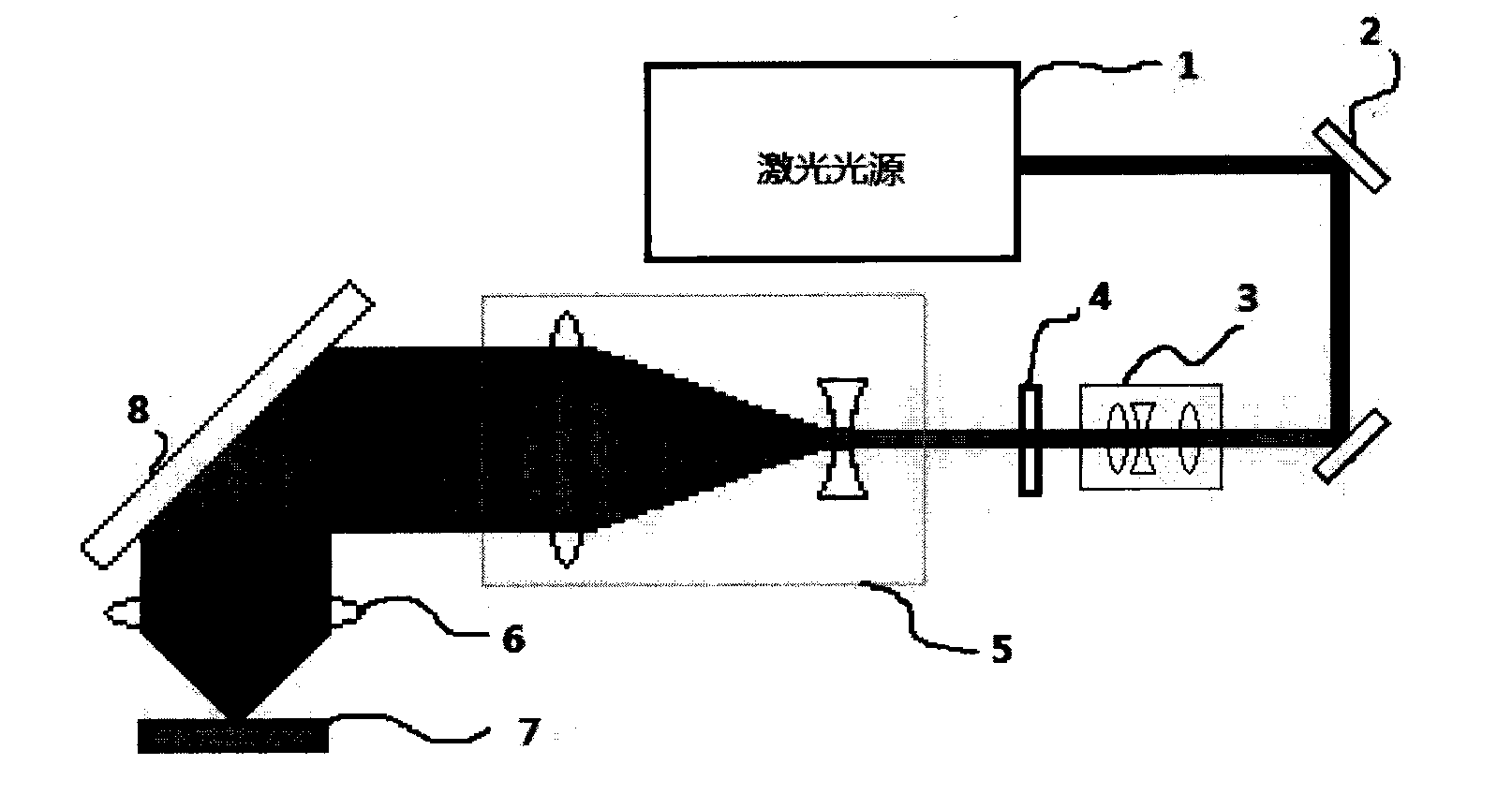
[0026] refer to figure 1 , to fabricate a laser direct writing device that includes real-time shaping of liquid crystal light valves. The laser light source 1 selected by this device is a picosecond pulse laser produced by Coherent Company, with a pulse width of 15 ps and a pulse repetition frequency of 15 kHz. The output formed by the laser light source 1 is deflected by the mirror group 2. The mirror group 2 includes 3 mirrors, which deflect the laser light emitted by the laser light source 1 to the required position and angle, and pass the pre-shaping from the center. Lens group 3. The front shaping lens group 3 includes two convex lenses and one concave lens, which expands the laser beam emitted by the laser light source 1 to a diameter of 15mm. The laser beam with a diameter of 15 mm emitted from the front shaping lens group 3 is irradiated on the liquid crystal light valve 4 . The liquid crystal light valve 4 is a LCX016AL-6 transmissive liquid crystal light valve pro...

Embodiment 2

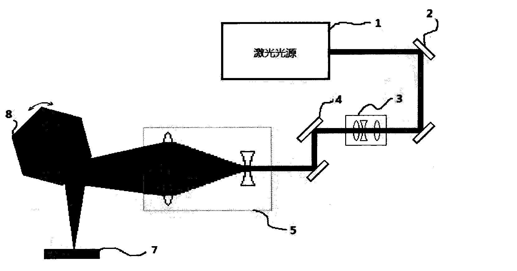
[0028] refer to figure 2, to fabricate a laser direct writing device that includes real-time shaping of liquid crystal light valves. The laser light source 1 selected by this device is a pulse laser produced by Beijing Guoke Century Laser Technology Co., Ltd., with a pulse width of 20 ns and a pulse repetition frequency of 1 kHz. The output formed by the laser light source 1 is deflected by the mirror group 2. The mirror group 2 includes two mirrors, which deflect the laser light emitted by the laser light source 1 to the required position and angle, and pass the pre-shaping from the center. Lens group 3. The front shaping lens group 3 includes 2 pieces of convex lens and 1 piece of concave lens, and its shaping diaphragm. The laser light emitted by the laser light source 1 is shaped to 20mm×15mm, and the aberration is eliminated. The laser beam emitted from the front shaping lens group 3 is irradiated on the liquid crystal light valve 4 . The liquid crystal light valve 4...


PUM


Abstract

The invention relates to a method and a device of laser direct writing machining and belongs to the technical field of laser machining. The device is a laser machining device which comprises a laser light source, a reflector group, a front reshaping lens group, a liquid crystal light valve, a rear reshaping lens group, a focusing lens, materials to be processed and a reflector or a multi-surface rotating reflector. The laser light source is used to generate laser to be machined, after beams of the laser to be machined are expanded by the front lens group, the laser is reshaped by the liquid crystal light valve, and then the beams of the laser to be machined are expanded by the rear lens group and the laser is converged on the materials to be machined, so that the laser direct writing machining can be achieved. The laser machining device can machine in a high speed direct writing mode, and at the same time, meets requirements of special machining shapes, achieves wide range of laser direct writing machining and has good practical significance.

Description

technical field [0001] The invention relates to a novel processing system, in particular to a method and device for laser direct writing processing, and belongs to the technical field of laser processing. Background technique [0002] Laser direct writing is a laser processing technology that focuses the laser on the material, and processes the required pattern on the surface of the processed material through high temperature ablation. The existing laser direct writing technology usually achieves processing by converging laser light to one point. By controlling the precise and regular movement of the convergence point, the required graphics can be directly written. However, affected by the laser ablation time and the moving speed of the focus point, the efficiency of this direct writing scheme is low and the processing cost is high. [0003] As a shaping device, the liquid crystal light valve can achieve precise shaping of the injected laser beam. The liquid crystal light...

Claims


Application Information

Patent Timeline
IPC IPC(8): B23K26/073B23K26/38G02B27/09
Inventor 赵天卓余锦樊仲维黄科聂树真
Owner ACAD OF OPTO ELECTRONICS CHINESE ACAD OF SCI
Why Eureka
Try Eureka