Hydraulic control mechanism for vanes

A technology of hydraulic control mechanism and vane

Active Publication Date: 2012-12-26
胡阳
View PDF7 Cites 16 Cited by
  • Summary
  • Abstract
  • Description
  • Claims
  • Application Information

AI Technical Summary

Problems solved by technology

Since the vane pump is used to pump the fluid, it generally pumps the liquid with high viscosity such as oil. If the oil is immersed in the gap between the vane and the vane groove, this will affect the normal operation of the vane from the rotor. protruding, which will affect the working stability of the vane pump

Method used


Image

  • Hydraulic control mechanism for vanes
  • Hydraulic control mechanism for vanes
  • Hydraulic control mechanism for vanes

Examples


Embodiment Construction

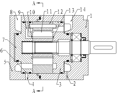
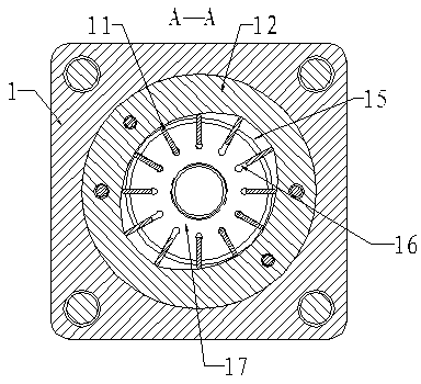
[0028] The structure of the vane pump with hydraulic control mechanism of the present invention includes a casing, a stator 12 and a rotor 17 . Both ends of the housing are respectively provided with an inlet 14 and an outlet 8, the inlet 14 is used to communicate with the oil tank, and the outlet 8 is used to communicate with the outlet pipeline in the hydraulic system.

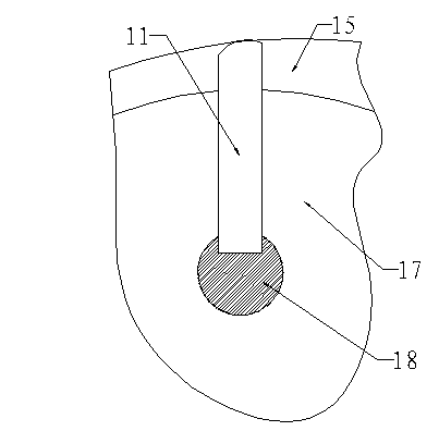
[0029] The rotor 17 is arranged in the stator 12 coaxially with a gap, the rotor 17 can rotate in the stator 12, and both the rotor 17 and the stator 12 are arranged in the casing. A plurality of vane slots 16 are arranged on the rotor 17 along its radial direction, and the openings of the vane slots 16 are located on the outer peripheral surface of the rotor 17 . Each vane slot 16 is provided with a vane 11 , and the dimension of the vane 11 along the axial direction of the rotor 17 is equal to or slightly smaller than the dimension of the vane slot 16 along the axial direction of the rotor 17 . When the r...


PUM


Abstract

The invention discloses a hydraulic control mechanism for vanes. The hydraulic control mechanism for the vanes solves the problem that vanes can still extend to the outside of a rotor when the existing common vane pump does not work, so that the energy consumption of the vane pump is large. The vane pump structurally comprises a shell, a stator and a rotor, wherein the rotor is arranged in the stator in a rotatable mode, a plurality of vane grooves are radially arranged in the rotor, the vane grooves are internally provided with the vanes in a sliding way, and the vanes can partially extend out of the radial outside of the rotor, or retract into the rotor. A cavity is formed between the rotor and the stator, and is provided with a fluid suction zone, a fluid compression zone and a vane retraction zone, the shell is internally provided with a chamber communicated with the cavity, and the chamber is communicated with the outside through a fluid inlet and a fluid outlet. When the rotor is required to idle, pressure fluid is introduced into the chamber so as to enable the vanes to stably retract into the rotor.

Description

technical field [0001] The invention relates to a vane pump, in particular to a hydraulic control mechanism for controlling the movement of vanes on the rotor of the vane pump. Background technique [0002] There are three main structural forms of pumps used to pump fluid, namely plunger pumps, gear pumps and vane pumps. Vane pumps are widely used in many mechanical fields because of their excellent working performance. [0003] The structure of the existing vane pump mainly includes a stator and a rotor, the rotor is rotatably arranged in the stator, and a cavity is formed between the stator and the rotor. The inner wall surface of the stator is approximately elliptical, so that a fluid suction area, a fluid compression area and a vane retraction area are formed in the cavity. A plurality of vane slots are arranged in the rotor along its radial direction, and a vane is slidably arranged in each vane slot. After the rotor rotates, under the action of centrifugal force, the...

Claims


Application Information

Patent Timeline
Patent Type & Authority Applications(China)
IPC IPC(8): F04C14/00F04C2/344
Inventor 王新彪胡凯
Owner 胡阳
Why Eureka
Try Eureka