
Combined type jet flow fish pump with automatic control system

An automatic control system and combined technology, applied in fishing, application, animal husbandry, etc., can solve the problems of difficulty in removing blocked obstacles, waste of time and electric energy, small jet suction flow, etc., and achieve simple structure and convenient operation , avoid the effect of blocking

Inactive Publication Date: 2013-01-02
FISHERY MACHINERY & INSTR RES INST CHINESE ACADEMY OF FISHERY SCI
View PDF2 Cites 11 Cited by
  • Summary
  • Abstract
  • Description
  • Claims
  • Application Information

AI Technical Summary

Problems solved by technology

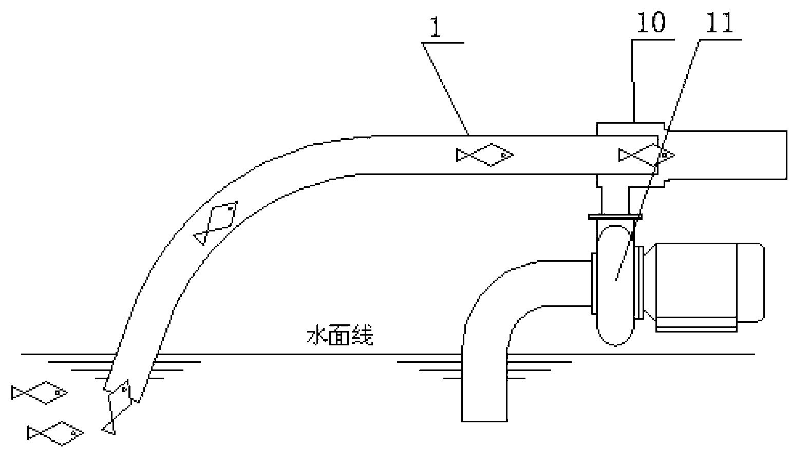
[0004] When the above-mentioned jet-type fish-suction pump sucks live fish, because the jet-flow suction flow is small, and the instinctive habit of the fish is to escape in the opposite direction, it is difficult for live fish to enter the fish-suction pipe, and often the fish-suction pump works for a long time, and few fish are obtained. , usually the ratio of fish to water is about 1:10, which is inefficient and wastes a lot of time and electricity;
[0005] Simultaneously, in the actual ocean fish suction operation, the hydrophobic holes of the hydrophobic cone 2 are often blocked by sundries such as baths, jellyfish, and plastic sheets floating in the water. The fish are sucked on the inner wall of the hydrophobic conical tube and cause the hydrophobic conical tube 2 to block. At this time, once the hydrophobic conical tube 2 is blocked, it is difficult to remove the blocked obstacle in the pipeline.

Method used


Image

  • Combined type jet flow fish pump with automatic control system
  • Combined type jet flow fish pump with automatic control system
  • Combined type jet flow fish pump with automatic control system

Examples


Embodiment Construction

[0028] The present invention will be further described below in conjunction with specific examples.

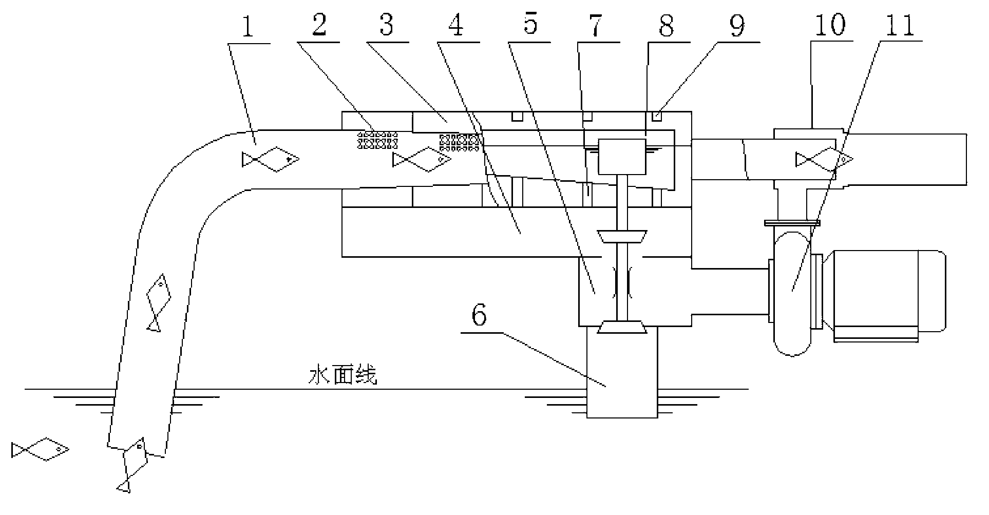
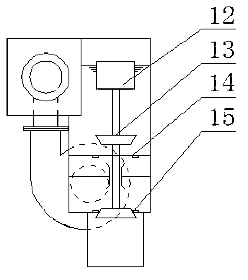
[0029] Such as Figure 2~4 As shown, a jet type fish suction pump device with an automatic control system includes a fish suction pipe 1, a hydrophobic cone 2, a jet device 10, a water pump 11, and the large end of the hydrophobic cone 2 is connected to the fish suction pipe, and the small end is connected to the jet The suction port of the device 10 is connected, the discharge port of the water pump 11 is connected with the injection chamber of the ejector 10, the water inlet of the water pump 11 is connected with the converter box 5, and also includes a water transfer adjustment water tank group sleeved on the outside of the hydrophobic cone pipe, the water transfer adjustment The box group includes a drainage box 3, a steady flow box 4, a flow conversion box 5, and an outer water pipe 6; The water boards are separated to form at least two water-separating chambers. The low...


PUM


Abstract

The invention relates to a combined type jet flow fish pump with an automatic control system. The combined type jet flow fish pump comprises a diaphragm-type pressure difference switch, two guide pipes which are communicated with each other are respectively arranged at the two ends of a diaphragm, one ends of the guide pipes are communicated to the walls of a front fish suction pipe a large end of a drainage taper pipe, and the other ends of the guide pipes are communicated to the walls of a front jet device suction port on a small end of the drainage taper pipe; and an upper end of a bidirectional valve rod is provided with an electric rod which is connected with the diaphragm-type pressure difference switch, the diaphragm-type pressure difference switch controls to drive the electric rod according to the pressure difference which is generated by the two sides of the diaphragm, when the pressure difference is increased, the electric rod drives the bidirectional valve rod to move downwards to close an upper valve opening and open a lower valve opening, so that the pressure difference is reset to normal, the electric rod is reset, the electric rod drives the bidirectional valve rod to move upwards to open the upper valve opening and close the lower opening. The combined type jet flow fish pump is convenient to operate, the drainage taper pipe can be prevented from being blocked due to over high fish water density, the blockage problem of the drainage taper pipe can be automatically solved, and the combined type jet flow fish pump is enabled to reliably operate.

Description

technical field [0001] The invention relates to a combined jet fish suction pump, in particular to a combined jet fish suction pump with an automatic control system Background technique [0002] China is a big country in aquatic product breeding. With the modernization of fishery, fish suction pumps have been put into use more and more as related supporting equipment for cage fish farming. At present, different styles of fish suction pumps have been developed at home and abroad. Such as centrifugal fish suction pump, pneumatic fish suction pump, vacuum type fish suction pump, jet type fish suction pump, etc. Among them, the jet type fish suction pump has many advantages, such as less damage to live fish, simple structure, and easy to manufacture. Convenient, low cost and so on. [0003] Existing jet-type fish suction pumps, such as figure 1 Shown, comprise a fish sucking pipe 1 and be connected with 2 big ends of hydrophobic conical pipe, the small end of hydrophobic conic...

Claims


Application Information

Patent Timeline
IPC IPC(8): A01K79/00
Inventor 徐英士曹建军毛燕文王君门涛
Owner FISHERY MACHINERY & INSTR RES INST CHINESE ACADEMY OF FISHERY SCI
Learn More