Micro acceleration transducer based on silicon substrate giant magnetoresistance effect

An acceleration sensor and acceleration technology, applied in the field of micro-inertial navigation, can solve the problems of complex manufacturing process, low yield, sensitivity drift, etc., and achieve the effects of reasonable structure design, simple design and convenient use.

Inactive Publication Date: 2013-01-02
ZHONGBEI UNIV
View PDF3 Cites 24 Cited by
  • Summary
  • Abstract
  • Description
  • Claims
  • Application Information

AI Technical Summary

Problems solved by technology

[0002] At present, the commonly used detection methods of micro-mechanical acceleration sensors are piezoresistive, capacitive, piezoelectric and tunnel effect, etc. The piezoresistive is based on the principle of piezoresistive effect of highly doped silicon. Pressure-sensitive devices have a strong dependence on temperature, and the bridge detection circuit composed of pressure-sensitive devices will also cause sensitivity drift due to temperature changes; the improvement of capacitive precision is to increase the capacitance area, due to the miniaturization of devices , its accuracy is difficult to improve due to the reduction of the effective capacitance area
The sensitivity of the piezoelectric effect nano sensor is easy to dri

Method used


Image

  • Micro acceleration transducer based on silicon substrate giant magnetoresistance effect
  • Micro acceleration transducer based on silicon substrate giant magnetoresistance effect
  • Micro acceleration transducer based on silicon substrate giant magnetoresistance effect

Examples


Embodiment Construction

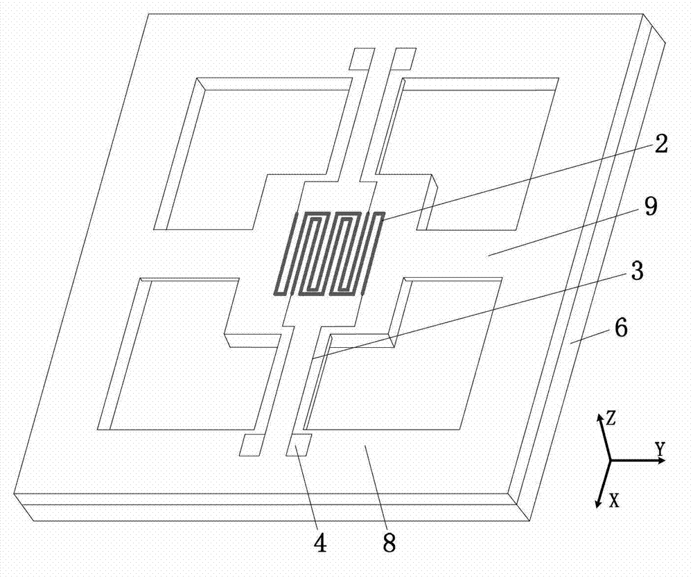
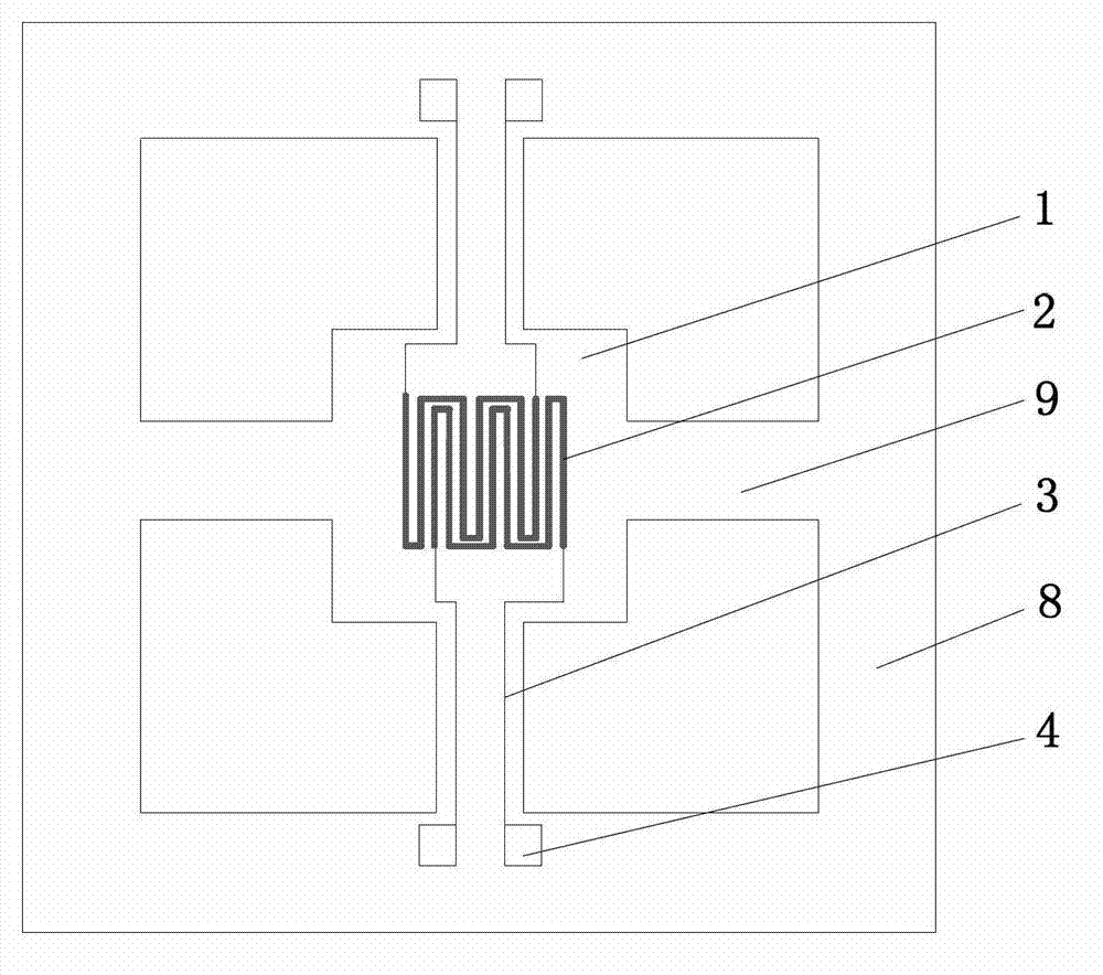
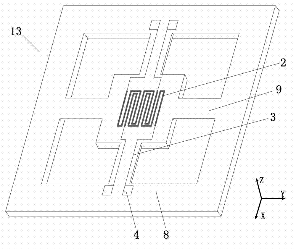
[0026] Embodiments of the present invention are described in detail below, examples of which are shown in the drawings, wherein the same or similar reference numerals designate the same or similar elements or elements having the same or similar functions throughout. The embodiments described below by referring to the figures are exemplary only for explaining the present invention and should not be construed as limiting the present invention.

[0027] In the description of the present invention, it should be understood that the orientations or positional relationships indicated by the terms "center", "upper", "lower", "front", "rear", "left", "right" etc. are based on the attached The orientation or positional relationship shown in the figure is only for the convenience of describing the present invention and simplifying the description, and does not indicate or imply that the referred device or element must have a specific orientation, be constructed and operated in a specific ...


PUM


Abstract

The invention discloses a micro acceleration transducer based on a silicon substrate giant magnetoresistance effect, which mainly comprises a bonding substrate, an iron magnetic membrane and an acceleration sensitive body, wherein the iron magnetic membrane is arranged in a rectangular groove (that is, a bottom groove) in the bonding substrate; the acceleration sensitive body is arranged above the bonding substrate and is connected with the bonding substrate; and the acceleration sensitive body comprises a sensitive mass correspondingly arranged above the bottom groove, a giant magnetic-sensing resistor arranged on the upper surface of the sensitive mass and corresponding to the iron magnetic membrane in position, a cantilever arranged around the sensitive mass, and a support frame body arranged on the outer side of the cantilever. The giant magnetic-sensing resistor layer vibrates in the direction perpendicular to the upper surface of the iron magnetic membrane and along with the sensitive mass. The micro acceleration transducer adopts an integral structure design, is reasonable in structure, simple in detection circuit, convenient to use, good in reliability, and suitable for miniaturization.

Description

technical field [0001] The invention relates to the related field of micro-inertial navigation technology, in particular to a micro-mechanical acceleration sensor based on the giant magnetoresistance effect. Background technique [0002] At present, the commonly used detection methods of micro-mechanical acceleration sensors are piezoresistive, capacitive, piezoelectric and tunnel effect, etc. The piezoresistive is based on the principle of piezoresistive effect of highly doped silicon. Pressure-sensitive devices have a strong dependence on temperature, and the bridge detection circuit composed of pressure-sensitive devices will also cause sensitivity drift due to temperature changes; the improvement of capacitive precision is to increase the capacitance area, due to the miniaturization of devices , its accuracy is difficult to improve due to the reduction of the effective capacitance area. The sensitivity of the piezoelectric effect nano sensor is easy to drift, requires f...

Claims


Application Information

Patent Timeline
IPC IPC(8): G01P15/105
Inventor 王莉郑伦贵李锡广李孟委刘俊崔敏
Owner ZHONGBEI UNIV
Why Eureka
Try Eureka