
Accuracy design method based on frequency domain error distribution for ultraprecise fly cutting machine tool

An error allocation and ultra-precise technology, applied in stone processing equipment, fine working devices, manufacturing tools, etc., can solve the problems of not considering the frequency domain error requirements of the workpiece, poor processing quality and reliability of the workpiece, and poor adaptability, etc., to achieve design Excellent flexibility and adaptability, strong reliability and good adaptability

Active Publication Date: 2013-01-09
HARBIN INST OF TECH
View PDF3 Cites 4 Cited by
  • Summary
  • Abstract
  • Description
  • Claims
  • Application Information

AI Technical Summary

Problems solved by technology

[0004] The purpose of the present invention is to solve the problem that the existing ultra-precision flying cutting machine tool design does not consider the frequency domain error requirements on the surface of the workpiece, the processing quality and reliability of the workpiece are poor, and the problem of poor adaptability when applied to large optical systems is provided. A precision design method for ultra-precision fly-cutting machine tools based on frequency-domain error distribution

Method used


Image

  • Accuracy design method based on frequency domain error distribution for ultraprecise fly cutting machine tool
  • Accuracy design method based on frequency domain error distribution for ultraprecise fly cutting machine tool

Examples


specific Embodiment approach 1

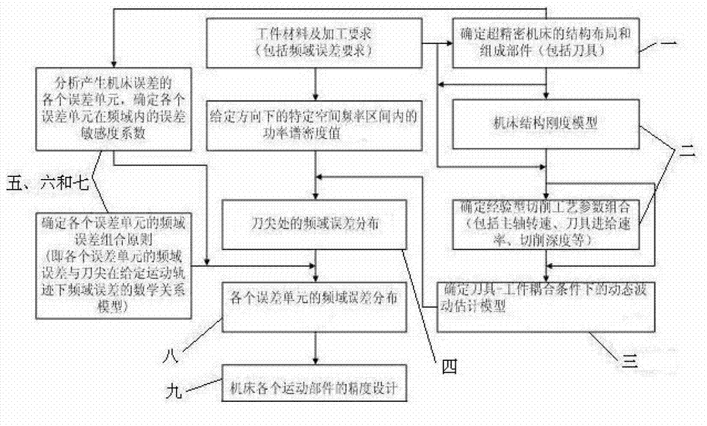
[0017] Specific implementation mode one: combine figure 1 Describe this embodiment, the specific steps of a kind of precision design method of ultra-precision flying cutting machine tool based on frequency domain error distribution of this embodiment are:

[0018] Step 1. According to the processing requirements of the optical workpiece, that is, the given evaluation of the error of the optical element to be processed in a certain spatial frequency interval, that is, the power spectral density of the frequency domain error, expressed in PSD, to determine the structural layout and components of the ultra-precision machine tool ;

[0019] Step 2. Determine the cutting process parameters according to the characteristics of the tool, the structural stiffness model of the machine tool and the material properties of the workpiece; the machine tool stiffness model is obtained by the finite element method, and the cutting process parameters refer to the spindle speed, the tool feed ra...

Embodiment

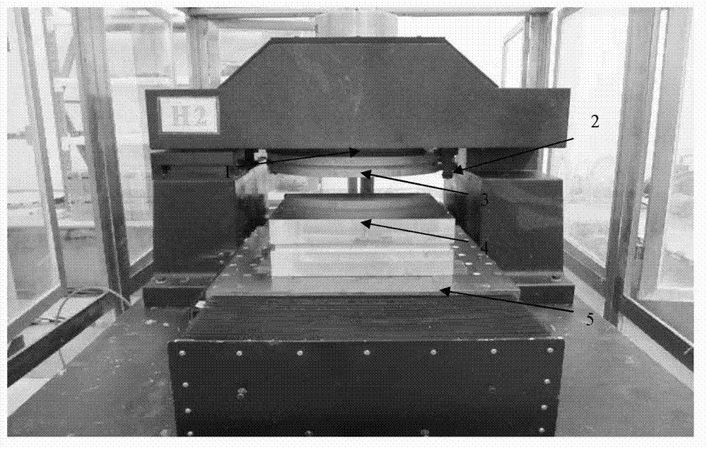
[0035] In order to further illustrate the present invention, in conjunction with figure 1 and figure 2 To illustrate this embodiment, the KDP crystal element used in the inertial confinement laser nuclear fusion system not only has a very high error requirement in the space domain, but also has a high error requirement in the frequency domain. The intermediate frequency error of the surface shape of the KDP crystal element, its main influence on the beam quality is to cause the decrease of the center brightness and make it broaden, which is an important reason for nonlinear self-concentration, and has a great influence on the safe operation of the laser system. harm. The spatial frequency interval corresponding to the intermediate frequency error is 0.03mm -1 -1 , that is, the spatial domain period range is 0.12mm2 mm. In this embodiment, the present invention is described by taking the data as an example of the target frequency domain error requirement of the workpiece su...


PUM


Abstract

The invention discloses an accuracy design method based on frequency domain error distribution for an ultraprecise fly cutting machine tool, which relates to an accuracy design method for an ultraprecise fly cutting machine tool and is used for solving the problems of poor processing quality and poor reliability of a workpiece and poor adaptability to a large-sized optical system since the frequency domain error requirement of a workpiece surface is not considered in the conventional design of an ultraprecise fly cutting machine tool. The design method mainly comprises the following steps of: I, determining a dynamic fluctuation estimation model under a tool and workpiece coupling condition; II, obtaining frequency domain error distribution on a tool nose; III, analyzing error units in which fly cutting machine tool errors occur; VI, determining the frequency domain error combination principle of each error unit; IV, determining the error sensitivity coefficient of each error unit relative to the tool nose in a frequency domain; and V, determining the frequency domain error distribution of each error unit in a certain spatial frequency section. The accuracy design method is applied to accuracy design of the ultraprecise fly cutting machine tool.

Description

technical field [0001] The invention relates to an ultra-precision machining machine tool precision design method, in particular to an ultra-precision fly-cutting machine tool precision design method based on frequency domain error distribution and suitable for processing optical crystals. Background technique [0002] Optical crystal is a kind of optical element material with great application value, which can be used to manufacture lenses, prisms, modulation elements, polarizing elements, etc. In large-scale inertial confinement laser fusion systems, optical components have extremely high surface quality requirements. This high requirement is not only reflected in the control of spatial domain errors, but also in the control of wavefront quality in the entire spatial frequency band. Because the low-frequency wavefront distortion error of the optical element directly determines the focal spot distribution of the laser beam, and the medium and high-frequency wavefront distor...

Claims


Application Information

Patent Timeline
Patent Type & Authority Applications(China)
IPC IPC(8): B28D5/00
Inventor 梁迎春陈国达孙雅洲张强张飞虎刘海涛陈万群苏浩
Owner HARBIN INST OF TECH
Learn More