
Vacuum drying device and drying method

A vacuum drying device and vacuum pump technology, applied in the direction of drying solid materials, local agitation dryers, and static material dryers, etc., can solve the problem that the degree of drying of materials cannot meet the process standards, the degree of drying cannot meet the standards, and the exchange of internal and external materials is slow, etc. problems, to achieve the effect of increasing the drying area, preventing material agglomeration, and saving energy

Active Publication Date: 2013-01-09
JIANGSU SHENJIU CHEM FIBER CO LTD
View PDF6 Cites 9 Cited by
  • Summary
  • Abstract
  • Description
  • Claims
  • Application Information

AI Technical Summary

Problems solved by technology

However, because the material in the vacuum drying container is not easy to stir, the drying rate is low, and the material in the container will agglomerate, resulting in the degree of drying of the material that cannot meet the process standard.
The prior art usually adopts the method of gas fluidization to solve this problem, but it is impossible to use gas to fluidize the material under the condition of high vacuum
Using mechanical force to turn the material is also a method, but the exchange of internal and external materials is very slow in this method. Some materials located in the center of the container may always be in the center during the turning, and there is also the problem of uneven drying and the drying degree cannot meet the standard.

Method used


Image

  • Vacuum drying device and drying method

Examples


Embodiment Construction

[0020] The specific embodiment of the present invention will be further described in detail below in conjunction with the accompanying drawings. The above and other objects, features and advantages of the present invention will be apparent to those skilled in the art from the detailed description of the present invention.

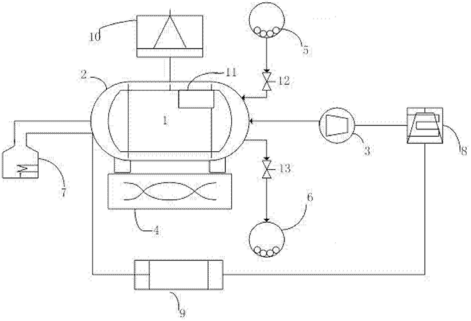
[0021] The following is a preferred embodiment of a vacuum drying device proposed by the present invention, such as figure 1 as shown,

[0022] figure 1 Among them, the horizontal tank body 1 is equipped with a heating jacket 2, and the horizontal tank body 1 is connected with the vacuum pump 3, the vibrating device 4, the feed port 5, and the discharge port 6 respectively, and the feed port isolation valve 12 connects the horizontal tank body 1 is isolated from the material inlet 5, and the material outlet isolation valve 13 isolates the horizontal tank body 1 from the material outlet 6, and these two isolation valves are in a closed state before working...


PUM


Abstract

The invention discloses a vacuum drying device and a method for drying materials by the aid of the vacuum drying device. The technical scheme mainly includes that the vacuum drying device comprises a horizontal tank, a feed port, a discharge port, a feed port isolation valve, a discharge port isolation valve, a vacuum pump and a heating device, the horizontal tank is respectively connected with the feed port, the discharge port and the vacuum pump, the horizontal tank is respectively isolated from the feed port and the discharge port by the feed port isolation valve and the discharge port isolation valve, the horizontal tank is provided with a heating jacket, and the heating jacket is connected with the heating device. The vacuum drying device is characterized by further comprising a vibrating device connected with the horizontal tank. The vacuum drying device is mainly used for drying the materials at a low temperature in a vacuum environment and liquefying the materials by means of mechanical vibration, material drying efficiency and drying degree are improved by heating and evacuating, and the vacuum drying device is particularly applicable to heat sensitive materials, anaerobic materials or materials with special drying requirements.

Description

technical field [0001] The invention relates to a vacuum drying device, in particular to a vacuum vibration drying device, and also relates to a method for drying materials using the vacuum drying device. Background technique [0002] Vacuum drying has been widely used in chemical, pharmaceutical, food and other industries for drying heat-sensitive materials and other additives. Vacuum drying can dry the material at a lower temperature (40°C to 75°C), which can ensure that the material will not be discolored or deteriorated due to excessive temperature during the drying process. However, because the material in the vacuum drying container is not easy to stir, the drying rate is low, and the material in the container will agglomerate, resulting in the degree of drying of the material not meeting the process standard. In the prior art, gas fluidization is usually used to solve this problem, but the gas cannot be used to fluidize the material under the condition of high vacuum...

Claims


Application Information

Patent Timeline
Patent Type & Authority Applications(China)
IPC IPC(8): F26B9/08F26B7/00
Inventor 金家齐邱国全张治义李永强朱希访肖建国
Owner JIANGSU SHENJIU CHEM FIBER CO LTD
Learn More