Optical system for laser-induced detection
An optical system and laser-induced technology, applied in optics, optical components, material excitation analysis, etc., to achieve the effect of avoiding gas breakdown
- Summary
- Abstract
- Description
- Claims
- Application Information
AI Technical Summary
Problems solved by technology
Method used
Image
Examples
Embodiment 1
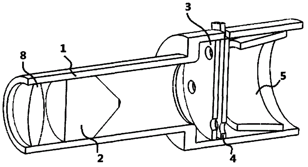
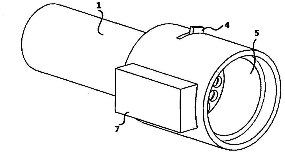
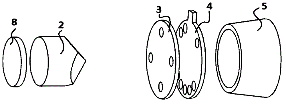
[0030] refer to figure 1 , figure 2 and image 3 , to fabricate an optical system for laser-induced detection. The outer sleeve 1 is made of welded stainless steel, and the inside is a threaded structure, and the optical element is tightened and fixed by a metal ring containing external threads. Along the light passing sequence, the first optical element is the focusing lens group 8, and the second optical element is the beam splitter 2, which is used to disperse the incident laser light for induction into 4 beams. The structure is as follows Figure 5 . The third optical element is the spectroscopic shielding plate 3, which is made of an aluminum sheet with a thickness of 1 mm, and contains four light holes with a diameter of 3 mm, which are arranged in a circular array at an angle of 90°. The structure is as follows Image 6 , the light split by the dichroic prism 2 exits through the four light holes. The fourth optical element is the beam selection baffle 4, on which ...
Embodiment 2
[0032] refer to Figure 4 , to fabricate an optical system for laser-induced detection. The outer sleeve 1 is made of aluminum plate, the inside is a sliding sleeve structure, and each element has a sleeve outside. The positioning of the optics is achieved by tightening the screws. Along the light passing sequence, the first optical element is the beam splitter 2, which is used to disperse the incident laser light for induction into 8 beams, such as Figure 8 . The second optical element is the beam-splitting baffle 3, which is made of a steel sheet with a thickness of 0.5 mm and contains 8 light holes with a diameter of 5 mm. The light split by the beam-splitting prism 2 is emitted through the 8 light holes. The third optical element is the beam selection baffle 4, on which 20 holes are arranged in an array with equal angular intervals along a circle with a diameter of 50 mm. By rotating the beam selection baffle 4, 2, 4, 6, and 8 laser beams can pass through the beam Sel...
Embodiment 3
[0034] refer to Figure 4, to fabricate an optical system for laser-induced detection. The outer sleeve 1 is made of aluminum plate, the inside is a sliding sleeve structure, and each element has a sleeve outside. The positioning of the optics is achieved by tightening the screws. Along the light passing sequence, the first optical element is the beam splitter prism 2, which is used to disperse the incident laser light for induction into two layers, each layer has 8 beams, such as Figure 9 . The second optical element is the beam-splitting baffle plate 3, which is made of a steel sheet with a thickness of 1 mm. It contains two layers of 8 light holes with a diameter of 3 mm on each layer. The light split by the beam-splitting prism 2 passes through these 8 light holes. shoot out. The third optical element is the beam selection baffle 4, which is divided into two layers along a circle with a diameter of 50 mm at equal angular intervals, and 20 holes are arranged in an arra...
PUM
| Property | Measurement | Unit |
|---|---|---|
| thickness | aaaaa | aaaaa |
| thickness | aaaaa | aaaaa |
Abstract
Description
Claims
Application Information
 - R&D
- Intellectual Property
- Life Sciences
- Materials
- Tech Scout
- Unparalleled Data Quality
- Higher Quality Content
- 60% Fewer Hallucinations
Browse by: Latest US Patents, China's latest patents, Technical Efficacy Thesaurus, Application Domain, Technology Topic, Popular Technical Reports.
© 2025 PatSnap. All rights reserved.Legal|Privacy policy|Modern Slavery Act Transparency Statement|Sitemap|About US| Contact US: help@patsnap.com


