Device and method for detecting state of main circuit relay in DC power supply system

A technology of DC power supply system and state detection device, which is applied in the field of main circuit relay state detection device, which can solve the problems of poor work reliability, personal or equipment danger, and inability to judge whether the relay is stuck, etc., and achieves the effect of simple circuit structure and guaranteed safety

Inactive Publication Date: 2015-11-18
CHANGSHA UNIVERSITY
View PDF7 Cites 0 Cited by
  • Summary
  • Abstract
  • Description
  • Claims
  • Application Information

AI Technical Summary

Problems solved by technology

[0004] At present, for relay state detection, it is mainly to collect the current in the relay coil as the basis for whether the relay is working normally, but this method can only detect whether the controller or the battery management system (BMS) controls the relay, and cannot really judge Whether the main contact of the relay is open or closed, it cannot be clearly judged whether the relay is in a normal state or a fault state
For example, in the case of relay main contacts sticking (relay sticking, that is, at the moment of high-voltage contact, the main contacts of the relay generate an arc before contact, and the high-temperature arc burns the contacts, resulting in the phenomenon that the contacts cannot be disconnected normally), The disconnection of the relay is controlled by the main controller CPU of the DC system or the battery management system (BMS), but the controller cannot judge whether the relay is stuck, and the work reliability is poor. The staff often mistakenly think that the relay has disconnected the high-voltage power supply. If the staff At this time, when touching the high-voltage busbar for maintenance or installation, it will cause danger to people or equipment.

Method used


Image

  • Device and method for detecting state of main circuit relay in DC power supply system
  • Device and method for detecting state of main circuit relay in DC power supply system
  • Device and method for detecting state of main circuit relay in DC power supply system

Examples


Embodiment 1

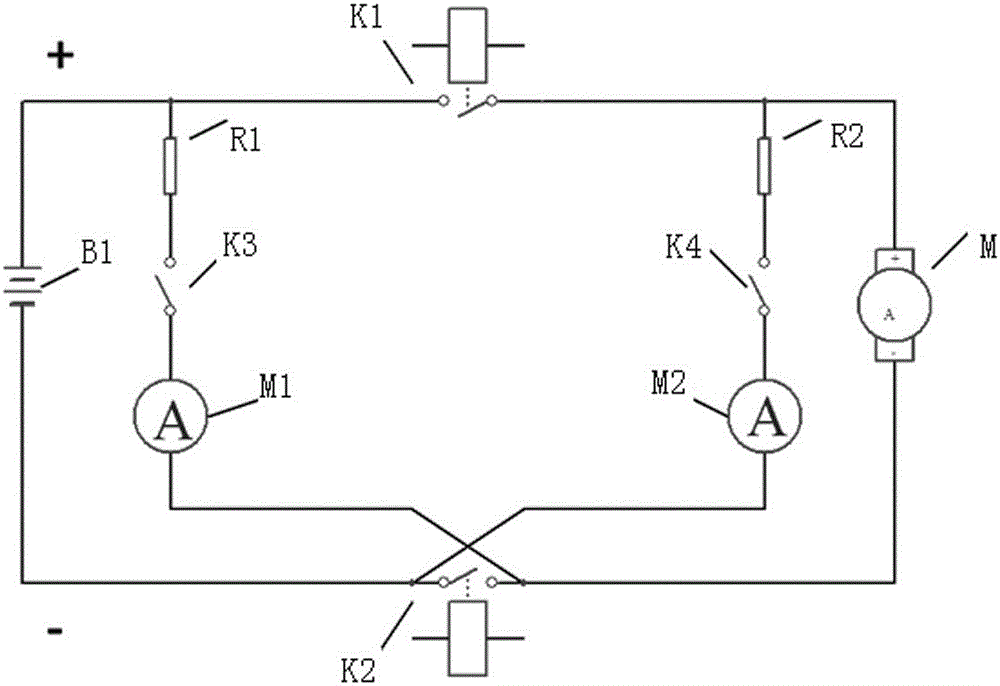
[0027] The main circuit relay state detection device of the DC power supply system of this embodiment includes a current-limiting resistor, an isolation switch and a current detection circuit, and the current-limiting resistor, the isolation switch and the current detection circuit are sequentially connected in series to form a detection branch, and the detection branches are cross-connected At both ends of the main contact of the main circuit relay.

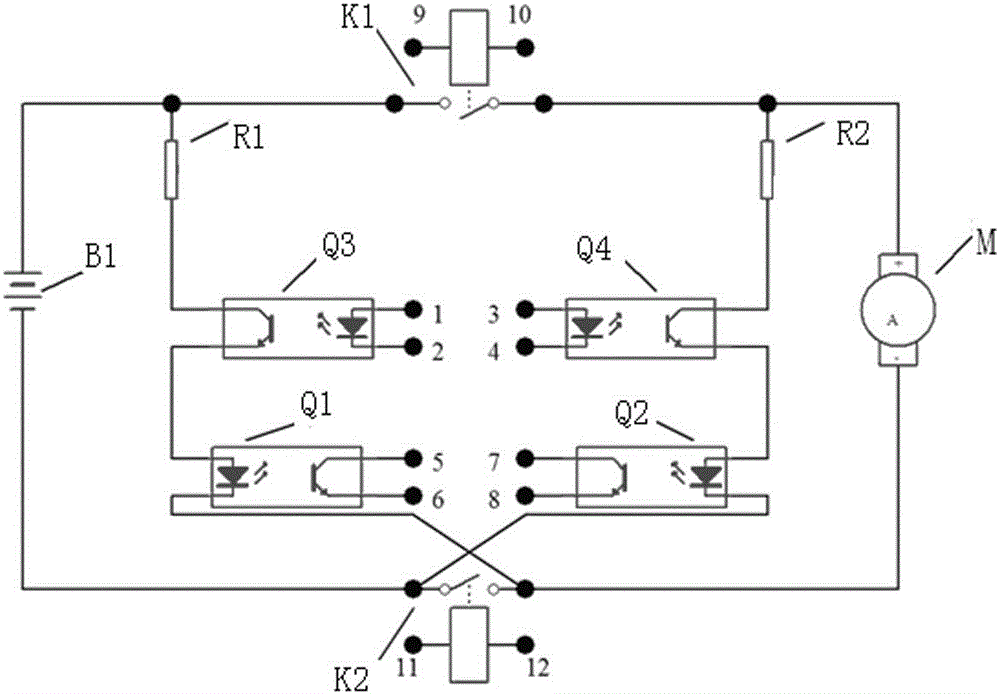
[0028] In this embodiment, the isolating switch is a photocoupler. The current detection circuit is a current detection circuit composed of a photocoupler, the current detection circuit is provided with a detection signal feedback terminal, the current detection circuit is connected in series with the current limiting resistor and the isolation switch through the LED end of the photocoupler, and the output terminal of the photocoupler It is the detection signal feedback terminal of the current detection circuit. When the LED ter...

Embodiment 2

[0044] The difference between this embodiment and Embodiment 1 is that the current detection circuit M1 and the current detection circuit M2 are resistors for converting current signals into voltage signals, and the current detection circuit is provided with a detection signal feedback terminal. At this time, by detecting The signal feedback terminal detects, that is, detects the voltage at both ends of the resistor that converts the current signal into a voltage signal to realize the state judgment.

[0045] The isolating switch K3 and the isolating switch K4 are combined switch circuits formed by using photocouplers.

[0046] All the other are with embodiment 1.

Embodiment 3

[0048] The difference between this embodiment and Embodiment 1 is that: the isolating switch K3 and the isolating switch K4 are signal relays.

[0049] All the other are with embodiment 1.


PUM


Abstract

The invention discloses a device and a method for state detection of a main loop relay of a direct-current power supply system. The device comprises current-limiting resistors, disconnecting switches and current detecting circuits, the current-limiting resistors, the disconnecting switches and the current detecting circuits are sequentially connected in series to form detecting branch circuits, and the detecting branch circuits are connected to two ends of a main contact of the main loop relay in a cross manner. The method is used for detecting the state of the main loop relay by the aid of the device for state detection of the main loop relay of the direct-current power supply system. The device is simple in circuit structure, can perform online real-time detection of the state of the main loop relay of the direct-current power supply system, can reliably detect the state of the main loop relay and precisely judges whether the relay is in the normal state or fault state, and thereby power output of a power supply device is well controlled, and personal and equipment safety is guaranteed beneficially.

Description

technical field [0001] The invention relates to a main circuit relay state detection device and method, in particular to a main circuit relay state detection device and method of a DC power supply system. Background technique [0002] With the increasing tension of fossil energy, the application requirements of energy saving and environmental protection are getting more and more attention. Therefore, various efforts to develop pure electric vehicles or hybrid vehicles in recent years are aimed at reducing energy consumption and pollution to the living environment. [0003] At present, the power supply system used in hybrid electric vehicles and pure electric vehicles is usually composed of multiple battery packs in series, and the DC bus voltage is as high as hundreds of volts, which is far beyond the safe voltage that the human body can bear. Once the high-voltage system fails , it is very dangerous for operation or maintenance personnel. The output and shutdown of the hi...

Claims


Application Information

Patent Timeline
Patent Type & Authority Patents(China)
IPC IPC(8): G01R31/327
Inventor 张镇林勇王子薇
Owner CHANGSHA UNIVERSITY
Why Eureka
Try Eureka