Device and method for seismic cross hole computed tomography (CT) detection and tomography of underground cave

A tomography, karst cave technology, applied in measurement devices, seismology, geophysical measurement and other directions, can solve the problems of imperfect detection method of karst cave detection technology, limited detection depth range, limited detection range, etc. , small size, simple equipment effect

Inactive Publication Date: 2013-01-09
NANJING UNIV
View PDF2 Cites 34 Cited by
  • Summary
  • Abstract
  • Description
  • Claims
  • Application Information

AI Technical Summary

Problems solved by technology

[0016] Although the well ground seismic detection method is easy to operate and has high accuracy, it also has the problems of limited detection depth range and serious ground interference, especially when construction is carried out on the roadside in urban areas, the impact of driving vehicle vibration cannot be ignored
[0017] Judging from the current research results, karst cave detection technology has the characteristics of imperfect detection methods, high cost, serious interference with urban construction, poor accuracy and limited detection range.
Especially in terms of detection depth, with the development of urban underground engineering depth (urban subways, underground shopping malls, etc.), several commonly used detection methods will gradually lose their advantages

Method used


Image

  • Device and method for seismic cross hole computed tomography (CT) detection and tomography of underground cave
  • Device and method for seismic cross hole computed tomography (CT) detection and tomography of underground cave
  • Device and method for seismic cross hole computed tomography (CT) detection and tomography of underground cave

Examples


specific Embodiment approach

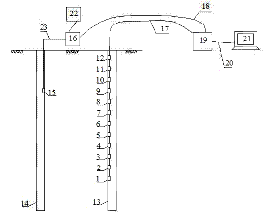
[0044] Such as figure 1 , 2 Shown, the specific embodiment of the present invention is as follows:

[0045] (1) Drill holes in the area to be detected (generally, the drill holes arranged by the survey plan can be divided into the first drill hole 13 and the second drill hole 14) to the required depth, and properly handle the inside of the drill hole: The rocks in the hole should be cleaned to ensure that the geophone and the electric spark source can go down to the required depth.

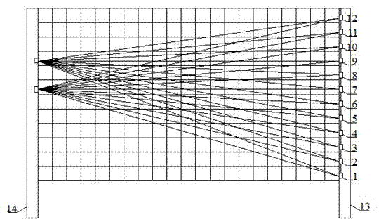
[0046] (2) Placement of geophones: put a series of geophones 1-12 into the first borehole 13, the vertical spacing of the geophones meets the design requirements, and the geophones are connected to the seismograph 19 through the first cable 17. Ensure that all 12 geophones are located below the groundwater level to ensure the quality of seismic wave reception.

[0047] (3) Placement of the seismic source: Put the electric spark seismic source 15 into the second borehole 14, connect with the exc...

example

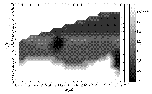
[0068] One section of a certain subway project passes through the limestone stratum, where small karst caves develop, and the size of the karst caves generally ranges from dozens of work points to 2m. The purpose of engineering exploration is to understand the karst development around the 20-40 m deep borehole. However, the thickness of the overburden layer on the rock mass is generally about 10-20m. Using geological radar detection, it is found that due to the strong attenuation of electromagnetic wave energy in the thick overburden layer, the detection range will be limited, and the detection results are not ideal. Later, the cross-hole CT method is adopted, the drilling depth is 50m, and the spacing is 20-50m.

[0069] Taking the cross-hole CT detection results of boreholes G72 and G73 as an example, the wave velocity contours in the rock body between the holes are as follows: image 3 As shown in , the low wave velocity (dark black area) in the figure is the location of th...


PUM


Abstract

The invention discloses a device for seismic cross hole computed tomography (CT) detection and tomography of an underground cave. The device comprises a string of detectors, an excitation device, an excitation control system, a first cable, a second cable, a third cable, a fourth cable, a seismograph and a computer. A vertical first drilling hole and a vertical second drilling hole are arranged on ground surface, the plurality of detectors are arranged in the first drilling hole and connected with the seismograph through the first cable, the excitation device is arranged in the second drilling hole, the excitation device can move up and down freely, the excitation device is connected with the excitation control system through the fourth cable, the excitation control system is connected with the seismograph through the second cable, and the seismograph is connected with the computer through the fourth cable. The invention further discloses a method for seismic cross hole CT detection and tomography of the underground cave. The method can detect the underground cave rapidly and effectively.

Description

technical field [0001] The invention relates to the field of detection of small underground karst caves, in particular to an underground karst cave seismic cross-hole CT detection and tomographic imaging device and method. Background technique [0002] Karst is a situation that is often encountered in engineering geological surveys in various aspects such as industrial and civil construction, roads, and railway environments. Due to the dissolution, the stone buds and karst grooves on the surface of the soluble rocks are uneven, and the underground karst caves destroy the integrity of the rock mass. Changes in karst hydrodynamic conditions cause cracks and subsidence in the upper covering soil layer. Underground karst is often manifested in the form of karst caves, underground corridors, and underground rivers, all of which affect the stability of building foundations to varying degrees. [0003] It is difficult to make a reasonable and accurate evaluation of the developmen...

Claims


Application Information

Patent Timeline
Patent Type & Authority Applications(China)
IPC IPC(8): G01V1/00
Inventor 许宝田阎长虹徐杨段成龙
Owner NANJING UNIV
Why Eureka
Try Eureka