
Device for detecting ion beam section density distribution and uniform ion beam distribution in real time

A density distribution and ion beam technology, applied in the field of semiconductor device manufacturing, can solve the problems of not being able to detect the beam profile and scan the beam distribution in real time, and achieve the effect of improving the beam shape and applicability

Active Publication Date: 2013-01-09
BEIJING SHUOKE ZHONGKEXIN ELECTRONICS EQUIP CO LTD
View PDF5 Cites 21 Cited by
  • Summary
  • Abstract
  • Description
  • Claims
  • Application Information

AI Technical Summary

Problems solved by technology

[0003] The present invention is aimed at the situation that the existing ion implanter technology cannot detect the beam profile and scan the beam distribution in real time, and proposes a new detection device, which replaces the original method of repeatedly moving and detecting by moving Faraday, directly The profile distribution of the beam spot and the scanning beam current distribution are obtained from the detection results of the device, so as to provide a hardware basis for real-time and accurate control of the distribution change of the beam current

Method used


Image

  • Device for detecting ion beam section density distribution and uniform ion beam distribution in real time
  • Device for detecting ion beam section density distribution and uniform ion beam distribution in real time

Examples


Embodiment Construction

[0014] The present invention is described in further detail below in conjunction with specific embodiment:

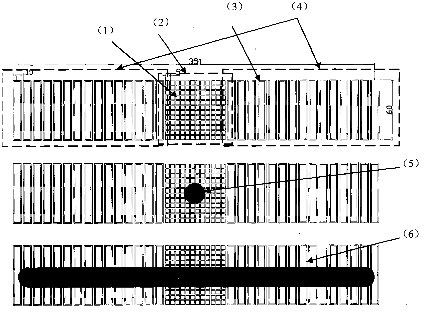
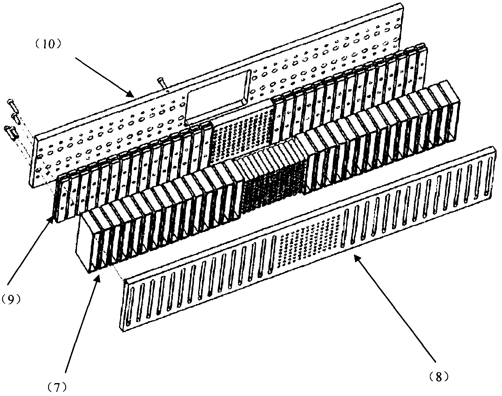
[0015] Such as figure 1 As shown, the Faraday array combination device consists of a two-dimensional Faraday array (2) in the middle and two one-dimensional Faraday arrays (4) on both sides. This installation method is suitable for bidirectional scanning ion implanters, that is, after scanning The beam shape is extended to both sides of the beam center. When the beam is in the focused state (5), all the beam is projected on the two-dimensional Faraday array (2), and by detecting the beam size of each small Faraday, the distribution of the beam density can be obtained in real time, so that it can be adjusted in real time Control parameters, change the shape of the beam profile, and obtain high-quality beams. When the beam current is in the scanning state (6), the beam current is distributed on the one-dimensional Faraday array (4) on both sides. By detecting the size o...


PUM


Abstract

The invention discloses an array composite Faraday cup capable of detecting beam spot section density distribution of ion beam current under a focusing condition and uniform beam distribution under a scanning condition. The array composite Faraday cup comprises a two-dimensional Faraday cup array (2) and two one-dimensional Faraday cup arrays (4), wherein the two-dimensional Faraday cup array (2) is positioned at the center, and the one-dimensional Faraday cup arrays (4) are positioned on two sides respectively. The array composite Faraday cup is characterized in that the two-dimensional Faraday cup array (2) at the center is used for detecting beam spot section density distribution of ion beams under the focusing condition (5), and the one-dimensional Faraday cup arrays (4) on the two sides are used for detecting uniform beam distribution of the ion beams under the scanning condition (6). By the aid of the array composite Faraday cup, distribution and state change of the ion beams can be detected in real time, and detection instantaneity and accuracy can be improved.

Description

technical field [0001] The invention relates to an ion beam current detection device for an ion implanter of semiconductor manufacturing equipment, belonging to the field of semiconductor device manufacturing. Background technique [0002] As the semiconductor integrated circuit manufacturing process becomes more and more miniaturized, the performance requirements for semiconductor manufacturing equipment are also getting higher and higher. The ion beam implanter is one of the most critical doping equipment in semiconductor device manufacturing. When the device manufacturing process enters the era of feature size below 90nm and wafer size of 300mm, in order to ensure the consistency of device performance on the entire wafer, ion beam implantation must be carried out. In the implant doping process, there are higher requirements for maintaining the uniformity of doping distribution throughout the wafer. Therefore, real-time and accurate detection of the shape and uniformity d...

Claims


Application Information

Patent Timeline
IPC IPC(8): H01J37/304H01J37/317G01T1/29
Inventor 孙勇彭立波谢均宇
Owner BEIJING SHUOKE ZHONGKEXIN ELECTRONICS EQUIP CO LTD
Learn More