
Method for correcting electronically programmable fuse wire device

A fuse and electronic technology, used in electrical components, semiconductor/solid-state device manufacturing, circuits, etc., to solve problems such as limited programming equipment and pins, limited application scope, and low process yield.

Inactive Publication Date: 2013-01-09
SHANGHAI HUALI MICROELECTRONICS CORP
View PDF3 Cites 2 Cited by
  • Summary
  • Abstract
  • Description
  • Claims
  • Application Information

AI Technical Summary

Problems solved by technology

[0002] There are three main types of traditional fuses: metal fuses that are blown by lasers (Laser Fuse), or metal fuses that are blown by high current (Metal Fuse) and polysilicon fuse (Poly Fuse). Existing commercially available products often face problems such as irreversibility due to the use of laser blowing, high-current blowing and other processes. High current will be limited by the design of programming equipment and pins; while Laser Fuse can only be carried out before chip packaging, the application range is limited, and the yield rate of the process is low

Method used

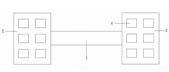
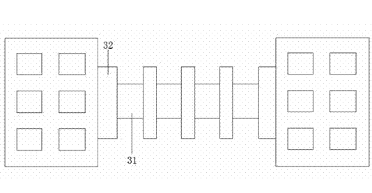

Image

  • Method for correcting electronically programmable fuse wire device
  • Method for correcting electronically programmable fuse wire device
  • Method for correcting electronically programmable fuse wire device

Examples


Embodiment Construction

[0019] The present invention will be further described below in conjunction with the accompanying drawings and specific embodiments, but not as a limitation of the present invention.

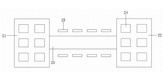
[0020] Such as figure 2 Shown is an electronically programmable fuse device improved by a modification method, including electrodes 21 and 22 and a polysilicon fuse 23 connected between the two electrodes, and 24 is a contact hole on the electrode, and the above-mentioned components are integrated into a on the substrate; wherein, an additional pattern 25 (Sub-resolution Assistant Feature, SRAF) with sub-resolution is added on the substrate on both sides of the polysilicon fuse 23 .

[0021] The so-called sub-resolution additional graphics are a kind of optical proximity correction method (OPC). The principle is to add additional graphics that cannot be resolved by the lithography machine around the normal graphics. These sub-resolution additional graphics cannot be resolved by the lithograph...


PUM


Abstract

The invention discloses a method for correcting an electronically programmable fuse wire device, which is suitable for an electronically programmable fuse wire device. The electronically programmable fuse wire device comprises two polysilicon electrodes and an electronically programmable fuse wire connected between the electrodes, wherein the electrodes and the electronically programmable fuse wire are positioned on a substrate; sub-resolution additional patterns are added at both sides of the electronically programmable fuse wire; and the sub-resolution additional patterns are used for changing the characteristic dimension of the electronically programmable fuse wire. The invention has the following beneficial effects: by adding the sub-resolution additional patterns, different characteristic dimensions can be formed in the polysilicon fuse wire, so that different current densities can be formed, and the electric migration phenomenon of the electronically programmable fuse wire can be enhanced, thereby enhancing the fusing performance of the electronically programmable fuse wire device.

Description

technical field [0001] The invention relates to the technical field of electronic programmable fuses, in particular to a method for correcting electronic programmable fuses. Background technique [0002] There are three main types of traditional fuses: metal fuses (Laser Fuse) that are blown by laser, or metal fuses (Metal Fuse) and polysilicon fuses (Poly Fuse) that are blown by high current. Commercially available products often face problems such as irreversibility due to the use of laser burnout and high-current burnout processes. For example, Metal Fuse or Poly Fuse needs to be performed with a large current, which will be limited by the programming equipment and pins. Design; while Laser Fuse can only be carried out before chip packaging, the application range is limited, and the yield rate of the process is low. [0003] Electronically Programmable Fuse (Electrically Programming Fuse, eFuse) is compiled based on the principle of electromigration. Compared with tradi...

Claims


Application Information

Patent Timeline
Patent Type & Authority Applications(China)
IPC IPC(8): H01L21/768
Inventor 俞柳江
Owner SHANGHAI HUALI MICROELECTRONICS CORP
Learn More