
Automatic spraying machine

A technology of automatic spraying and racking, which is applied in the direction of coating, spraying device, and device for coating liquid on the surface, etc. It can solve the problems of increasing cost, poor spraying effect of complex patterns, and waste of paint, etc.

Inactive Publication Date: 2013-01-16
JINHUI ZHONGSHAN METAL MFG
View PDF11 Cites 41 Cited by
  • Summary
  • Abstract
  • Description
  • Claims
  • Application Information

AI Technical Summary

Problems solved by technology

[0002] The last process of general parts in mechanical processing production is to paint the parts. The traditional painting is done manually, but because the paint itself contains heavy metals and harmful gases, it is inhaled by the staff during the painting process. It will cause poisoning and is extremely harmful to health, so now the paint workshops basically use automatic assembly lines for painting. The efficiency is improved, but the spraying effect of this kind of assembly line spraying on parts is limited to the uniform spraying of large areas, and the spraying effect of some complex patterns is not good, and it is difficult to control, and it will also cause waste of paint and increase the cost
Therefore, people have developed robotic spraying, which uses manipulators and programmed programs for spraying. This spraying effect is good, the efficiency is also high, and complex spraying can be completed, but the cost of the robot arm is very high. For small enterprises in mass production unrealistic

Method used


Image

  • Automatic spraying machine
  • Automatic spraying machine

Examples


Embodiment Construction

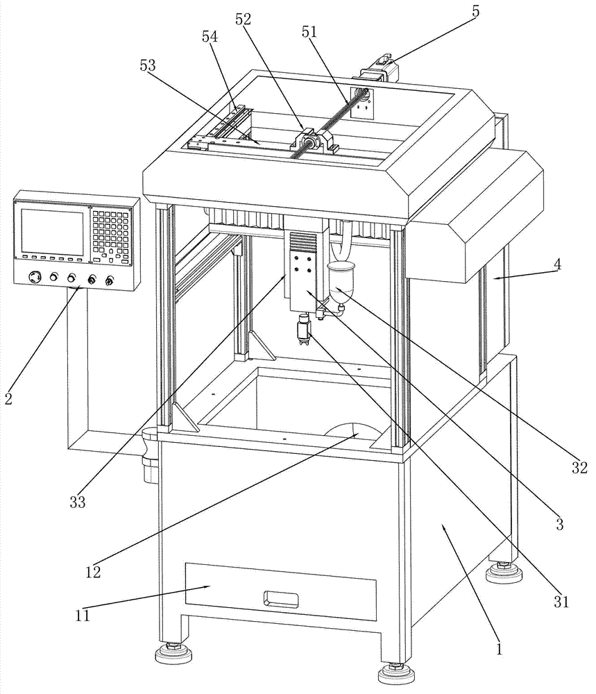
[0019] like figure 1 The shown automatic spraying machine includes a frame 1, and the frame 1 is a cavity shell with a window on the top to pick and place parts, and a shielding window can be set on the window opened, and the shielding window is working It is in the closed state to avoid oil splashing during spraying, and the shielding window is opened when parts need to be taken and placed, and the shielding window can be made of transparent material, so that the spraying situation can be observed at any time during work. There is a recovery tank 11 at the bottom of the frame 1. The recovery tank 11 is mainly used to recover the paint dripped during the spraying process. The recovery tank 11 is designed in the form of a drawer. When the waste in the recovery tank 11 is full, it can be removed from the machine. The bottom side of the frame 1 extracts the recovery tank 11, and then the waste materials are processed in a concentrated manner, which is beneficial to environmental ...


PUM


Abstract

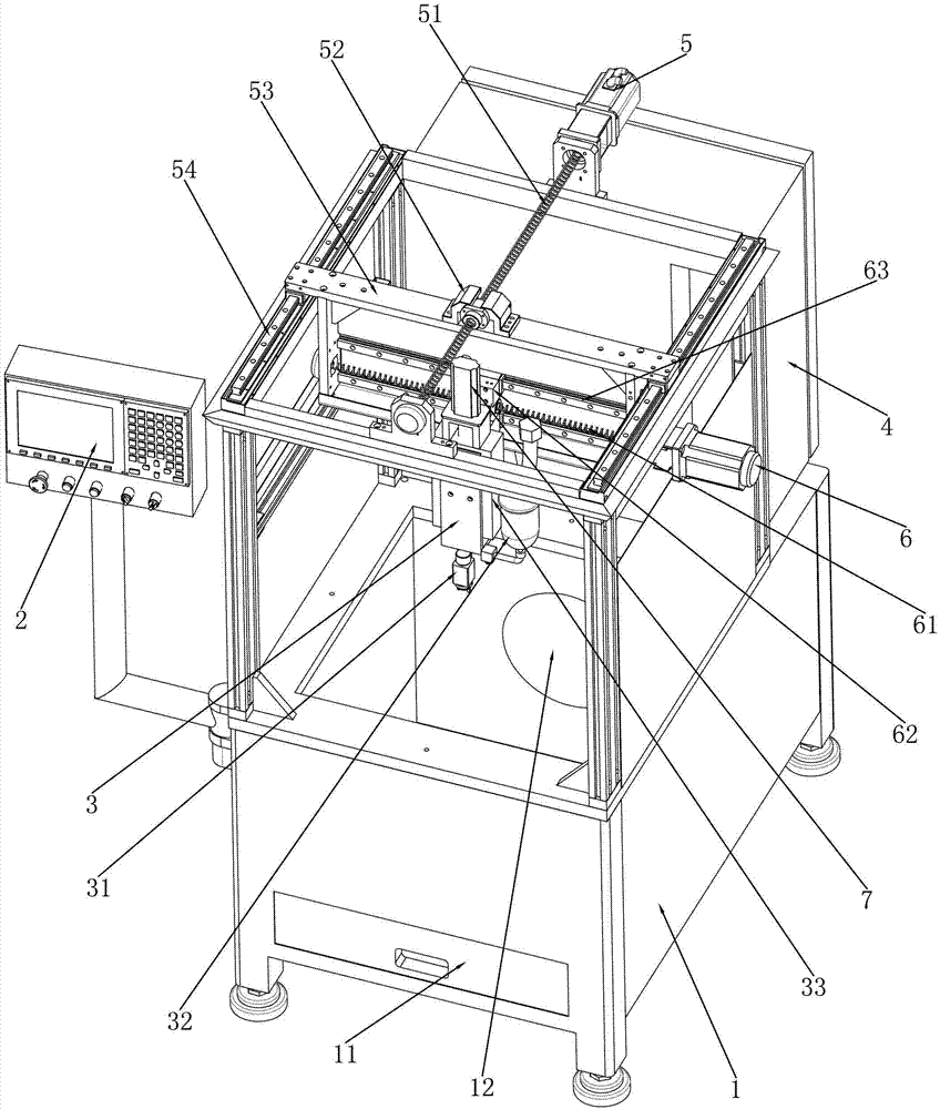
The invention discloses an automatic spraying machine which comprises a machine frame, an operation panel used for inputting and displaying work signals, and a control cabinet, wherein a Y-axis guide rail is arranged on the machine frame; a Y-axis guide frame capable of sliding on the Y-axis guide rail forwards and backwards is arranged on the Y-axis guide rail; an X-axis guide rail is arranged on the Y-axis guide frame; an X-axis guide frame capable of moving on the X-axis guide rail horizontally is arranged on the X-axis guide rail; a Z-axis guide rail is arranged on the X-axis guide frame; a Z-axis guide frame capable of moving on the Z-axis guide rail up and down is arranged on the Z-axis guide rail; an oil can for containing a coating material is arranged on one side of the Z-axis guide frame; a nozzle for spraying is also arranged below the Z-axis guide frame and is communicated with the oil can; an air pipe used for spraying the coating material is also connected with the nozzle; a Y-axis driving device capable of driving the Y-axis guide frame to move forwards and backwards is also arranged on the machine frame; an X-axis driving device capable of driving the X-axis guide frame to move horizontally is also arranged on the Y-axis guide frame; and a Z-axis driving device capable of driving the Z-axis guide frame to move up and down is arranged on the Z-axis guide rail.

Description

technical field [0001] The invention relates to painting equipment, in particular to automatic painting equipment. Background technique [0002] The last process of general parts in mechanical processing production is to paint the parts. The traditional painting is done manually, but because the paint itself contains heavy metals and harmful gases, it is inhaled by the staff during the painting process. It will cause poisoning and is extremely harmful to health, so now the paint workshops basically use automatic assembly lines for painting. The efficiency is improved, but the spraying effect of this assembly line spraying on the parts is limited to the uniform spraying of a large area, and the spraying effect of some complex patterns is not good, and it is difficult to control, and it will cause waste of paint and increase the cost. Therefore, people have developed robotic spraying, which uses manipulators and programmed programs for spraying. This spraying effect is good, ...

Claims


Application Information

Patent Timeline
IPC IPC(8): B05B13/04B05B15/04B05B15/12B05B13/02
Inventor 刘从高谭锦升蓝爱勇潘晓帆赵江平唐林新
Owner JINHUI ZHONGSHAN METAL MFG
Learn More