High-sensitivity strip drift detection device based on array infrared technology

A high-sensitivity, infrared technology, applied in the field of automatic control, can solve problems such as low stability, low sensitivity, and small measurement range, and achieve the effects of simple and easy installation, improved measurement resolution, and simple and intuitive calibration

Inactive Publication Date: 2013-01-16
WUHAN UNIV OF TECH
View PDF5 Cites 10 Cited by
  • Summary
  • Abstract
  • Description
  • Claims
  • Application Information

AI Technical Summary

Problems solved by technology

Therefore, even if the fluorescent tubes are landfilled or incinerated, these pollutants will eventually destroy the living environment of human beings in various forms and seriously endanger human health.
[0006] 2) An offset detection method based on Hall magnetic induction technology. This type of method is based on Hall magnetic induction technology, which effectively avoids the shortcomings of the previous scheme, such as low life, large environmental impact, and low sensitivity. However, due to the Hall magnetic induction technology itself It has the disadvantages of small measurement range, high energy consumption, and high price. Therefore, in actual use, the detection sensor based on this method not only has the disadvantages of short range, high energy consumption, and high price, but also because of its small measurement range. , resulting in too small distance between the detection sensor and the strip in the vertical direction, which is prone to collision, and then causes damage to the core components of the sensor detection unit, requiring frequent inspection and replacement, which not only increases its operating cost, It also affects its wide application in strip deflection control
[0007] 3) The offset detection method based on laser technology. This type of method is based on laser technology and has the advantages of large working distance, high sensitivity, low energy consumption, and low environmental pollution. However, the scope of application of this type of method is very narrow. The strip thickness requirements are very high, and it needs to be strictly controlled between 2-4mm, otherwise it cannot work normally, which makes this method unable to be applied to many thin plate processing procedures
In addition, this type of method has the disadvantages of short measuring range, high price, poor stability, difficult installation and maintenance, etc., and cannot meet the requirements of strip offset detection, so it has not been widely used.
[0008] In order to solve these problems, the invention patent with the patent number ZL200610124524.7 and the invention title "Strip Transmission Deviation Detection Sensor" discloses an infrared-based strip transmission deviation detection sensor, which effectively solves the above two types of problems. The sensor has the disadvantages of large pollution, low life, large environmental impact, high energy consumption, and high price, but it has difficulties in installation and calibration, low precision, low stability, serious drift, and sensitivity is affected by the transmitter and the sensor. Disadvantages such as the greater influence of the distance between receivers also affect its application in strip offset control

Method used


Image

  • High-sensitivity strip drift detection device based on array infrared technology
  • High-sensitivity strip drift detection device based on array infrared technology
  • High-sensitivity strip drift detection device based on array infrared technology

Examples


Embodiment Construction

[0026] The present invention will be described in further detail below in conjunction with the accompanying drawings and examples, but these examples should not be construed as limiting the present invention.

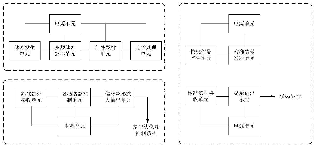
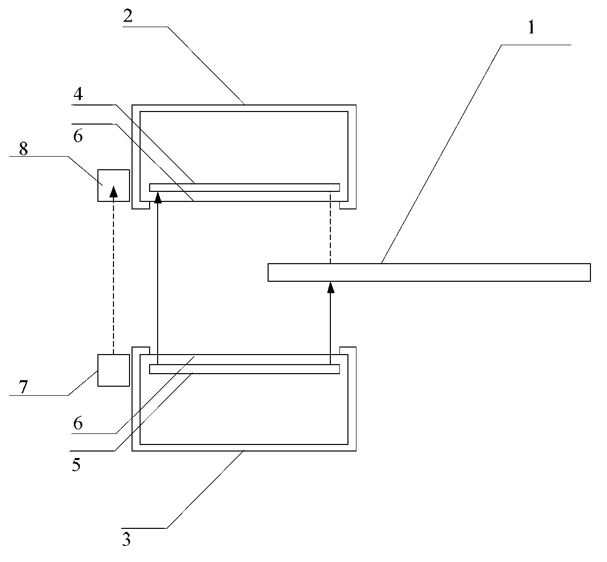
[0027] Depend on figure 1 It can be seen that the present invention includes three components: an infrared emitting device, an infrared receiving device and an auxiliary calibration device. Depend on figure 2It can be seen that the auxiliary calibration device in the embodiment of the present invention includes two parts: an infrared calibration signal transmitting module 7 and an infrared calibration signal receiving module 8, wherein the infrared calibration transmitting unit 7 of the auxiliary calibration device is on the same physical level as the infrared emitting device 3, The infrared calibration receiving unit 8 of the auxiliary calibration device and the infrared receiving device 2 are also located on the same physical device level. The interrelationships an...


PUM


Abstract

The invention relates to a high-sensitivity strip drift detection device based on an array infrared technology. The high-sensitivity strip drift detection device comprises an infrared emission device, an infrared receiving device and auxiliary calibrating devices, wherein the infrared emission device and the infrared receiving device are fixed at the two ends of an edge of a conveyed strip respectively; the fixing positions of the infrared emission device and the infrared receiving device correspond to each other; and the auxiliary calibrating devices are positioned on the two sides of each of the infrared emission device and the infrared receiving device. Due to the introduction of the infrared calibrating devices, the mounting process is simple and easy to implement, the calibrating operation is simple, convenient and intuitive, and the working load and the working strength for mounting and calibrating are greatly reduced; due to the introduction of a differential array, the measurement resolution ratio, the response speed and the sensitivity level of a system can be greatly increased with lower cost; and a pulse drive unit based on a complex frequency is designed in the infrared emission device, and an automatic gain control AGC unit is introduced into the infrared receiving device, so that the robustness, the reliability, the stability, the precision, the sensitivity and the anti-jamming capability of the device are greatly improved and the purpose of zero drift is achieved.

Description

technical field [0001] The invention belongs to the detection sensor technology in the field of automatic control, and is a high-sensitivity strip offset detection device based on array infrared technology, which is suitable for various strip production lines such as metal foil strips, cold-rolled steel strips, and paper strips. Background technique [0002] With the continuous development of the national economy, especially the continuous expansion of the manufacturing and real estate industries, the demand for steel in my country has been showing an upward trend. Traditional steel production and processing lines operate slowly, have low efficiency and high failure rate, so the automation and scale of steel production and processing lines are constantly improving. [0003] In the various strip production lines such as galvanizing line, tinning line, pickling line, etc. In the production process, the strip is prone to lateral swinging deviation and vertical up and down ups ...

Claims


Application Information

Patent Timeline
Patent Type & Authority Applications(China)
IPC IPC(8): G01B11/00G01B11/02
Inventor 肖攸安王霄鹏王伟王晶张润杜夏戴晓云王牛
Owner WUHAN UNIV OF TECH
Why Eureka
Try Eureka