Fiber Bragg grating sensing device

A sensing device and fiber grating technology are applied in the field of large-capacity and low-cost fiber grating sensing systems, and can solve the problems of small capacity and high cost

Inactive Publication Date: 2013-01-16
CHENGDU FORWARD TECH
View PDF4 Cites 7 Cited by
  • Summary
  • Abstract
  • Description
  • Claims
  • Application Information

AI Technical Summary

Problems solved by technology

[0008] The purpose of the present invention is to provide a low-cost and large-capacity fiber grating sensor multiplexing device to solve the problems of high cost and small capacity of the current fiber grating sensing system

Method used


Image

  • Fiber Bragg grating sensing device
  • Fiber Bragg grating sensing device
  • Fiber Bragg grating sensing device

Examples


Embodiment Construction

[0015] In order to describe the technical content, structural features, goals and effects of the present invention in detail, the following examples are given and described in detail with accompanying drawings.

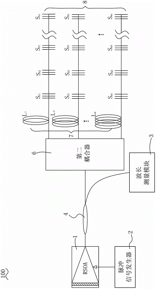
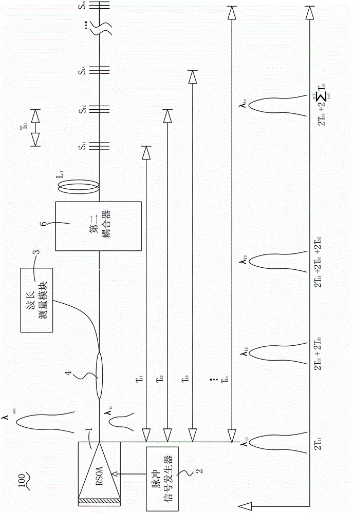
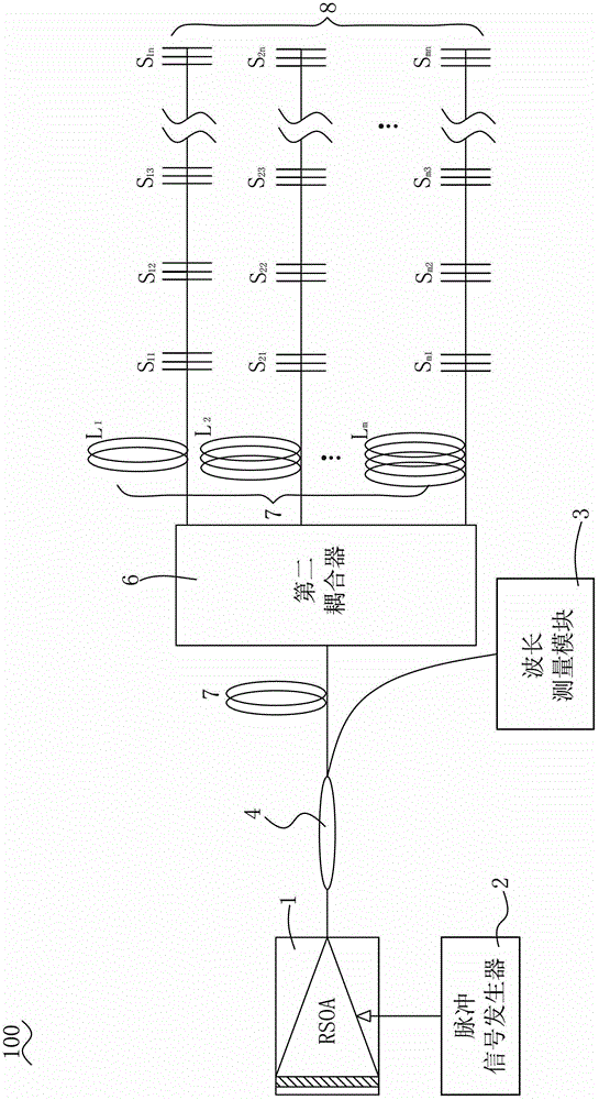
[0016] see figure 1 , a fiber grating sensing device of the present invention includes: a reflective semiconductor optical amplifier RSOA1, a pulse signal generator 2, a wavelength measurement module 3, a first coupler 4, an optical fiber (not shown in the figure), a first Two couplers 6 , at least one delay fiber 7 and a sensor array 8 .

[0017] see more figure 1 , the control input end of the reflective semiconductor optical amplifier RSOA1 is connected to the output end of the pulse signal generator 2; the optical fiber input / output end of the reflective semiconductor optical amplifier RSOA1 is connected to the input end of the first coupler 4.

[0018] The first coupler 4 is a 1*2 coupler. The first coupler 4 adopts a coupler with a splitting ratio of 10:90, w...


PUM


Abstract

The invention provides a fiber Bragg grating sensing device. A resonant cavity of the fiber Bragg grating sensing device consists of different sensors and a reflection-type semiconductor optical amplifier driven by pulse signals with different frequencies, so that different sensor signals can be read. The problem that the quantity of sensors in the traditional fiber Bragg grating wavelength division multiplexing technology is limited by the bandwidth of a light source is solved by a time division sensor access mode. Owing to a resonant cavity technology, sensing signals can be amplified in the cavity, so that the problem of low signal-to-noise ratio of sensing signals in the traditional time division multiplexing technology is solved. Time division multiplexing and wavelength division multiplexing are combined in a mixed multiplexing technology, so that the sensors are grouped, sensor groups are accessed in a parallel-serial matched mode, and sensor multiplexing capacity a system is greatly improved.

Description

technical field [0001] The invention relates to a high-capacity and low-cost optical fiber grating sensing system. Background technique [0002] Fiber Bragg grating sensors use the photosensitive properties of the fiber core material to form a structure with a periodic distribution of refractive index through ultraviolet light irradiation on the core. Under the condition of phase matching, the resonant wavelength modes are coupled to produce wavelength selectivity. The resonant wavelength of the fiber grating is affected by the external environment such as temperature and strain, so it can be used as a sensor to sense the change of external environmental parameters through the change of wavelength, and realize the measurement of various parameters. In addition to the advantages of light weight, no electromagnetic interference, high sensitivity, and corrosion resistance that ordinary fiber optic sensors have, it also has the characteristics of easy networking measurement, lar...

Claims


Application Information

Patent Timeline
Patent Type & Authority Applications(China)
IPC IPC(8): G01D5/36
Inventor 代勇波苗强
Owner CHENGDU FORWARD TECH
Why Eureka
Try Eureka