Detecting and testing device and method for inverter or charger
A technology of test equipment and chargers, which is applied in the direction of testing electrical devices in transportation, parts and instruments of electrical measuring instruments, etc., can solve the problems of electric shock danger, time-consuming and laborious, low work efficiency, etc. Simple process steps and the effect of reducing labor intensity
- Summary
- Abstract
- Description
- Claims
- Application Information
AI Technical Summary
Problems solved by technology
Method used
Image
Examples
Embodiment 1
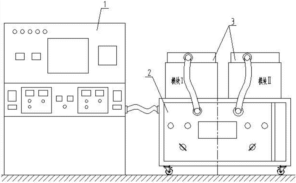
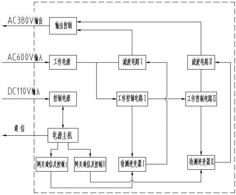
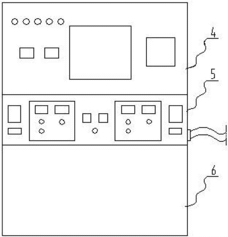
[0068] The inverter detection test equipment of the present invention includes a power supply host 1, a detection system 2 and a module to be detected 3. The module to be detected 3 is a three-phase inverter detection module I including a simulated dining car; or a simulated ordinary car The three-phase inverter detection module II; the power supply host 1 and the detection system 2 are electrically connected, and the power supply host 1 includes a DC power generation unit 4 located on the upper layer, a simulation over-phase unit 5 located on the middle layer, and a device The monitoring unit 6 on the lower level; the detection system 2 includes a box-like structure of the chassis assembly 7 and a control panel 9 provided on the front face of the chassis assembly 7 and a detection unit 8 installed in the chassis assembly 7;
[0069] The detection unit 8 includes a power line filter 81 arranged on the inner side of the chassis assembly 7 for the detection module I and the detectio...
Embodiment 2
[0090] The testing equipment for the inverter of the present invention includes a power host 1, a testing system 2 and a testing module 3, the testing module 3 is a testing module III including a single-phase inverter of a test system; the power host 1 and the detection system 2 are electrically connected. The power supply host 1 includes a DC power generation unit 4 located on the upper layer, an analog phase passing unit 5 located on the middle layer, and a monitoring unit 6 located on the lower layer; the detection system 2 includes A box-like structure of the chassis component 7 and a control panel 9 provided on the front face of the chassis component 7 and a detection unit 8 installed in the chassis component 7;
[0091] The detection unit 8 includes a current sensor 87 arranged on the inner side of the chassis assembly 7 for detecting the module III, and an electronic voltage detection board 86, a contactor 83 and wiring are sequentially arranged on one side of the current s...
Embodiment 3
[0111] The testing and testing equipment for the charger of the present invention includes a power supply host 1, a testing system 2 and a testing module 3. The testing module 3 is a testing module III including a testing system charger; the power supply host 1 and the testing system 2 Through electrical connection, the power supply host 1 includes a DC power generation unit 4 located on the upper layer, a simulation over-phase unit 5 located on the middle layer, and a monitoring unit 6 located on the lower layer; the detection system 2 includes a box-like structure The case assembly 7 and the control panel 9 arranged on the front face of the case assembly 7 and the detection unit 8 installed in the case assembly 7;
[0112] The detection unit 8 includes a current sensor 87 arranged on the inner side of the chassis assembly 7 for detecting the module III, and an electronic voltage detection board 86, a contactor 83 and wiring are sequentially arranged on one side of the current se...
PUM
 Abstract
Description
Claims
Application Information
 - R&D
- Intellectual Property
- Life Sciences
- Materials
- Tech Scout
- Unparalleled Data Quality
- Higher Quality Content
- 60% Fewer Hallucinations
Browse by: Latest US Patents, China's latest patents, Technical Efficacy Thesaurus, Application Domain, Technology Topic, Popular Technical Reports.
© 2025 PatSnap. All rights reserved.Legal|Privacy policy|Modern Slavery Act Transparency Statement|Sitemap|About US| Contact US: help@patsnap.com


