
Antenna housing for implementing antenna beamwidth switching by using artificial structure material

An artificial structure and antenna beam technology, applied in the field of radome, can solve the problems of narrow working bandwidth and large reflection, and achieve the effect of simple production process, simple maintenance, simple and novel design method

Active Publication Date: 2013-01-16
INST OF OPTICS & ELECTRONICS - CHINESE ACAD OF SCI
View PDF6 Cites 4 Cited by
  • Summary
  • Abstract
  • Description
  • Claims
  • Application Information

AI Technical Summary

Problems solved by technology

Since the design principle is based on the Fabry-Perot effect, the structure has a narrow operating bandwidth
In addition, due to the large reflection of the structure, it is necessary to design an additional matching circuit

Method used


Image

  • Antenna housing for implementing antenna beamwidth switching by using artificial structure material
  • Antenna housing for implementing antenna beamwidth switching by using artificial structure material
  • Antenna housing for implementing antenna beamwidth switching by using artificial structure material

Examples


Embodiment Construction

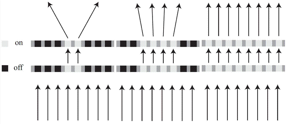
[0021] figure 1 The principle of the invention to realize the control of the width of the electromagnetic wave beam is described. Assuming that the material has an "on / off" effect on the transmission of electromagnetic waves, the beam width of the outgoing wave can be controlled by rationally arranging the switching area.

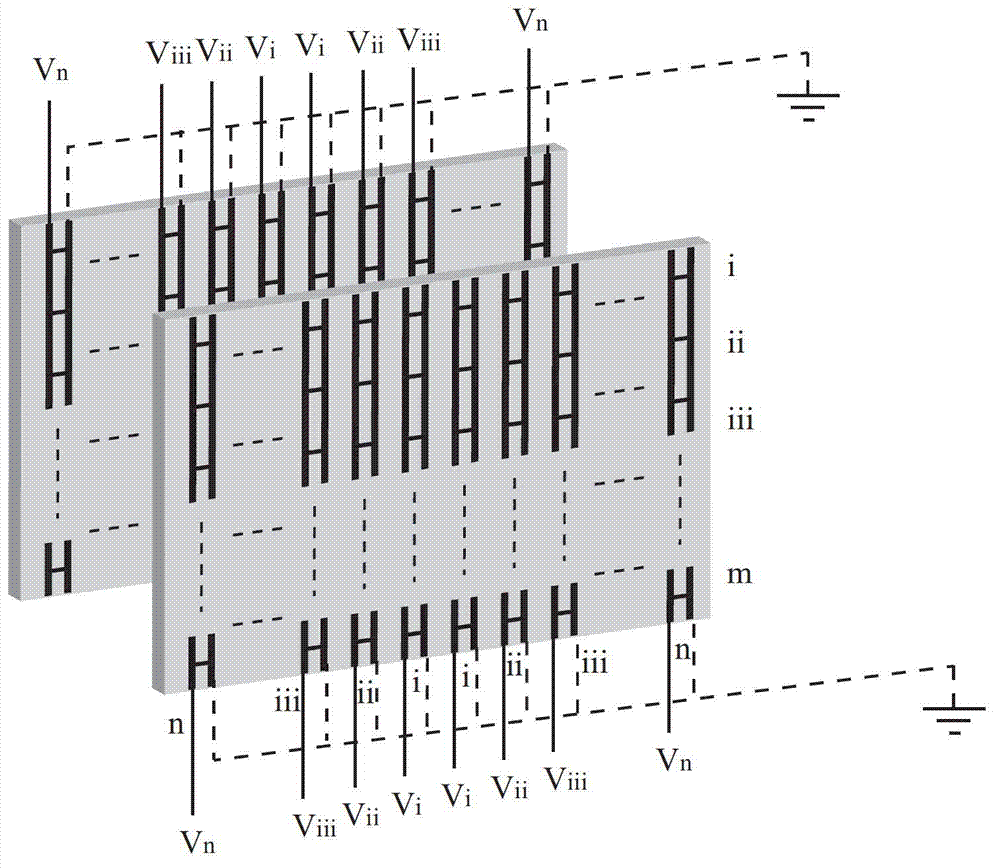
[0022] figure 2 A schematic diagram of the structure of the radome designed by the present invention is given. The radome is divided into upper and lower layers with similar structures. By reasonably controlling the "on / off" state of electromagnetic wave transmission in different columns, the control of the beam width of the transmitted wave can be realized.

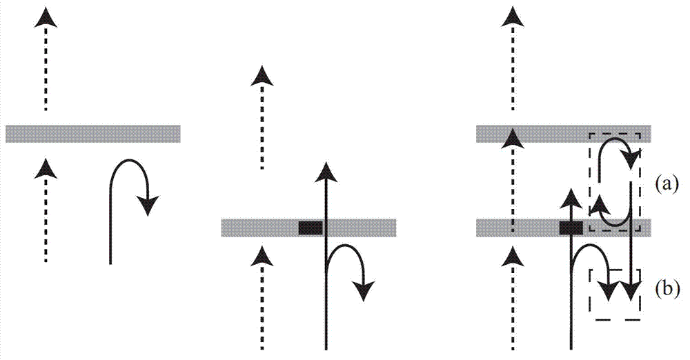
[0023] image 3 Describes the characteristics of electromagnetic waves when they pass through the lower microwave dielectric plate, the upper microwave dielectric plate and the overall structure of the radome. The dotted line represents the electromagnetic wave transmission behavior, and the reali...


PUM


Abstract

The invention discloses an antenna housing for implementing antenna beamwidth switching by using an artificial structure material. The antenna housing consists of two layers of microwave dielectric slabs which are printed with similar H-shaped metal wire structures; the upper-layer microwave dielectric slab is printed with 2n columns and m rows of H-shaped metal wire structures in the horizontal and longitudinal directions, and a microwave diode is arranged in each H-shaped metal wire structure; and the lower-layer microwave dielectric slab is printed with 2n columns and m rows of H-shaped metal wire structures in the horizontal and longitudinal directions, and a microwave diode and a chip resistor are arranged in each H-shaped metal wire structure. The upper-layer and lower-layer microwave dielectric slabs form the integral antenna housing, direct-current voltage is externally applied to the first row of metal wire in each H-shaped metal wire structure in the two layers of microwave dielectric slabs, diodes in each row of units have the same direct-current bias, the units in each row are connected in parallel, and by changing the externally applied direct-current voltage value, electromagnetic waves have high penetration or high absorption property. The antenna housing is loaded above an antenna, the externally applied direct-current voltage distribution is reasonably designed, and the width switching of antenna radiation beams can be realized; and the antenna housing is easy to manufacture and low in cost.

Description

technical field [0001] The invention relates to a radome for realizing switching of antenna beam width by using artificial structural materials, and belongs to the technical field of antenna manufacture. Background technique [0002] Traditionally, once the shape of the antenna is determined, its basic radiation performance will not change substantially, and the radiation beam width of the antenna will not change. There are two traditional methods to realize beam width control: changing the size of the antenna size parameter, or using phased array antenna to achieve phase compensation to change the radiation beam width. Beam control by changing the size of the antenna (not including changing the relative position of the elements in the antenna array) has disadvantages such as inflexibility, not real-time, and not easy to switch control, etc., which is not suitable for the fast and convenient signal processing requirements of modern technology. Although the use of phased arr...

Claims


Application Information

Patent Timeline
Patent Type & Authority Applications(China)
IPC IPC(8): H01Q1/42H01Q15/00
Inventor 黄成罗先刚赵泽宇蒲明博王民
Owner INST OF OPTICS & ELECTRONICS - CHINESE ACAD OF SCI
Learn More