Laser head device for solid laser

A laser head and laser technology, applied in the direction of lasers, laser parts, phonon exciters, etc., can solve the problems of low pumping efficiency and small absorption length of pumping light, achieve high-efficiency pumping, improve absorption efficiency, The effect of high beam quality

Inactive Publication Date: 2013-01-16
TECHNICAL INST OF PHYSICS & CHEMISTRY - CHINESE ACAD OF SCI
View PDF4 Cites 16 Cited by
  • Summary
  • Abstract
  • Description
  • Claims
  • Application Information

AI Technical Summary

Problems solved by technology

[0004] Therefore, the object of the present invention is to overcome the deficiencies that the pump light absorption length of the laser head device is small and the pumping efficiency is low when the side pumps the slats, and provide an improved laser head device for solid-state lasers

Method used


Image

  • Laser head device for solid laser
  • Laser head device for solid laser
  • Laser head device for solid laser

Examples


Embodiment 1

[0038] Embodiment 1 (Single-side single-channel four-pass pumping)

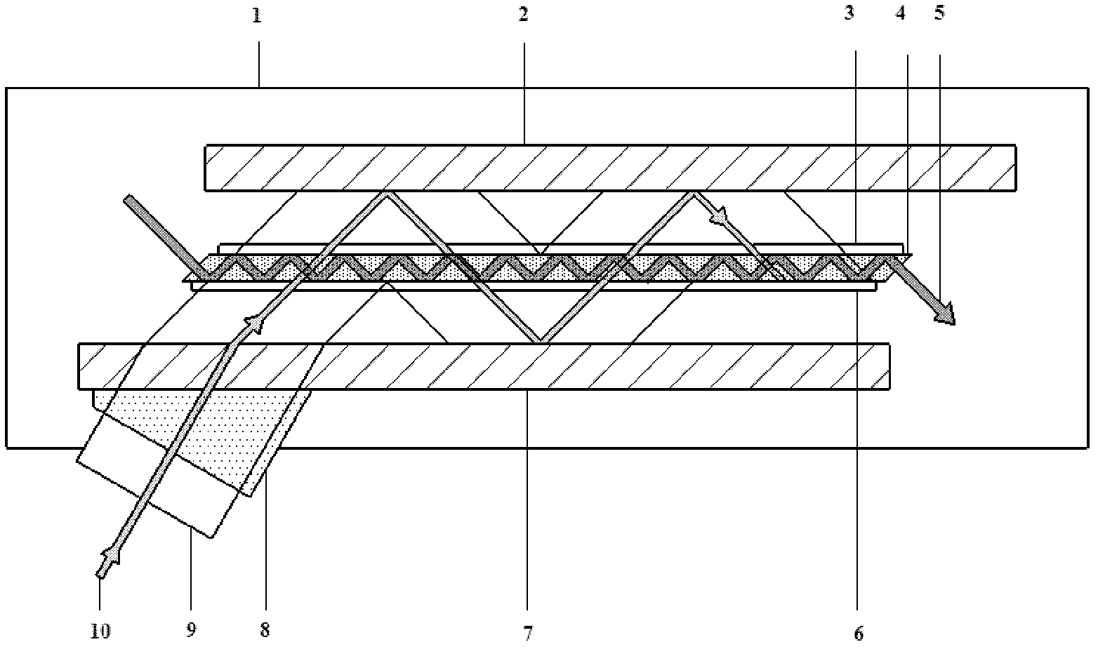
[0039] Figure 2a It is a schematic diagram of the structure of the laser head device in which the pump light pumps the slab along the side of the Z-shaped optical path according to Embodiment 1 of the present invention.

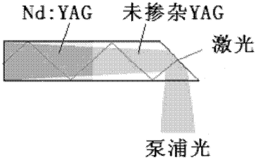
[0040] As shown in the figure, the laser head device includes a slab-shaped laser medium (for convenience, it will be simply referred to as "laser medium slab" or "slab" hereinafter) 4, and the laser medium slab is excited by the pump light to generate Laser output. The slab 4 is generally made of laser dielectric material, which can be crystal, glass or ceramics doped with Nd ions or Yb ions, including but not limited to: Nd:YAG, Nd:YVO for example 4 , Nd:GGG, Nd:YLF, Nd:YAP, Nd:S-FAP, Yb:YAG, Yb:YVO 4 , Yb:GGG, Yb:YLF, Yb:YAP, Yb:S-FAP crystals, Nd-doped ceramics, Yb-doped ceramics, Nd-doped glass, Yb-doped glass, ruby, titanium sapphire, etc. In this embodiment, the laser medium made...

Embodiment 2

[0054] Embodiment 2 (two-sided single-channel four-pass pumping)

[0055] according to image 3 The structure shown is to make a laser head device that pumps the slab along the side of the Z-shaped optical path, which is a double-sided single-channel four-pass Z-shaped pumping structure. It is improved on the basis of Embodiment 1, and one path of pumping light 12 is also added to one side of the window glass plate 2 . The pump light 12 passes through the pump light coupler 11 , emerges from the inside of the window glass plate at an angle of 45 degrees, and passes through the slat 4 four times.

Embodiment 3

[0056] Embodiment 3 (one-sided two-way four-pass pump)

[0057] according to Figure 4 The structure shown is to make a laser head device with pump light pumping the slab along the side of the Z-shaped optical path, which is a single-sided, double-channel, four-pass Z-shaped pumping structure. It is improved on the basis of Embodiment 1, and one path of pumping light 12 is also added on the other side of the window glass plate 7 . The pump light 12 passes through the pump light coupler 11 , emerges from the inside of the window glass plate at an angle of 45 degrees, and passes through the slat 4 four times. Optionally, the slats are also improved, the two ends of the slats 4 are no longer parallel, but vertical.


PUM


Abstract

The invention provides a laser head device for a solid laser, which comprises lath-shaped laser medium, a pump source, and two opposite glass plates arranged at the outer side of the large surface of the lath-shaped laser medium. Pump light produced by the pump source shines the lath-shaped laser medium through the wind glass plates so as to ensure that the laser medium is stimulated to be radiated and produces laser; and the pump light obliquely enters and penetrates through the lath-shaped laser medium through a transmission zone at the outer side of at least one wind glass plate, is reflected through a reflection zone of the other window glass plate, and then penetrates through the lath-shaped laser medium again, so that the pump light is reflected between the two window glass plates and penetrates through the lath-shaped laser medium at least two times. As the pump light penetrates through the lath-shaped laser medium repeatedly along a Z-shaped light path, the absorption length is optimally designed, and the absorption efficiency to the pump light by the laser medium is improved.

Description

technical field [0001] The invention relates to a solid-state laser, in particular to a laser head device for a solid-state laser, that is, a laser head device in which pump light pumps slabs along the side of a Z-shaped optical path. Background technique [0002] Due to the radial temperature gradient of traditional rod lasers, the thermal lens effect and birefringence effect are obvious under the pumping conditions of high-power semiconductor laser arrays, and it is difficult to achieve high beam quality and high average power laser output. For this reason, in 1969, General Motors of the United States proposed a solid-state laser model. The laser medium of the solid-state laser is in the shape of a slab, generally a rectangular sheet structure, with a large ratio of width to thickness, and the excited laser is transmitted along the Z-shaped optical path through total internal reflection inside the slab. This design is beneficial to eliminate the first-order thermal lens e...

Claims


Application Information

Patent Timeline
Patent Type & Authority Applications(China)
IPC IPC(8): H01S3/0941
Inventor 薄勇陈艳中彭钦军徐一汀许祖彦
Owner TECHNICAL INST OF PHYSICS & CHEMISTRY - CHINESE ACAD OF SCI
Why Eureka
Try Eureka