Heat engine with external heat source and associated power generation unit and vehicle

A heat engine and heat source technology, applied to engine components, steam engine devices, combustion engines, etc., can solve problems such as doubts about effectiveness, and achieve the effects of stress reduction, cost reduction, and volume reduction

Active Publication Date: 2013-01-23
H2P SYST
View PDF12 Cites 2 Cited by
  • Summary
  • Abstract
  • Description
  • Claims
  • Application Information

AI Technical Summary

Problems solved by technology

Converting this expelled energy into mechanical energy by common means

Method used


Image

  • Heat engine with external heat source and associated power generation unit and vehicle
  • Heat engine with external heat source and associated power generation unit and vehicle
  • Heat engine with external heat source and associated power generation unit and vehicle

Examples


Embodiment Construction

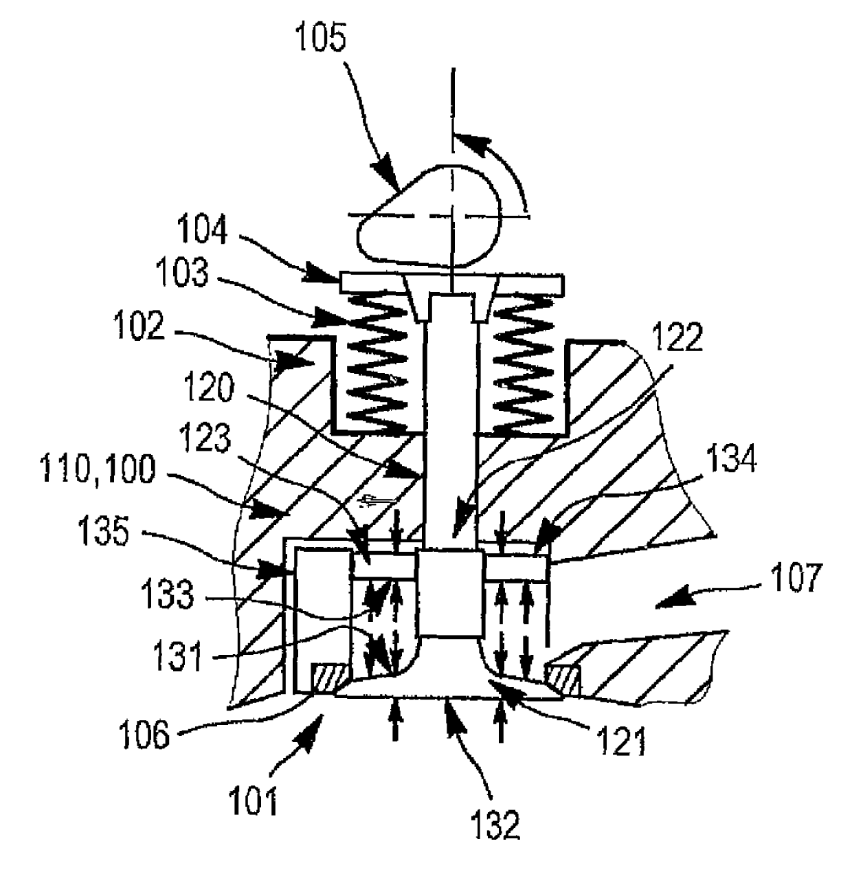
[0050] The mechanical power generation unit shown in FIG. 1 comprises a heat engine 1 and an internal combustion engine 2 . The heat engine includes a circular piston 13 which has reciprocating linear motion and is connected to the power shaft 5 .

[0051] The circular piston 13, viewed from above in FIG. 1 and shown in section in FIG. 10, is mounted in a sealed and axially translational manner in a cylinder 15 having an axis 13a which is parallel to the axis of the circular piston. common. Not shown in FIG. 1 but conventionally, the circular piston 13 is connected with the crankshaft 16 integrated with the power shaft 5 to convert the reciprocating motion of the circular piston into the rotational motion of the crankshaft or vice versa according to the flow direction of mechanical energy. It converts the rotary motion of the crankshaft into the reciprocating motion of the circular piston.

[0052] On the side away from the crankshaft, i.e. above the circular piston in a con...


PUM


Abstract

The invention relates to a heat engine comprising means for: compressing a cooled working gas, heating the compressed working gas using an external heat source, expanding the heated compressed working gas, cooling the working gas using a heat exchanger with a cold source, and, subsequently, returning the cooled working gas into the compression means.

Description

technical field [0001] The present invention relates to heat engines with external heat sources, and associated power generation units and transport means. The invention also relates to the recovery of exhaust heat, in particular for applications on any type of transport, in particular ground, sea or air transport, and also for stationary engine applications. Background technique [0002] Various embodiments of heat engines operating with an external heat source are known. However, these heat engines have low efficiency and low power density (per unit mass and volume). [0003] Heat loss from an internal combustion engine is the main cause of its low efficiency. Legal restrictions on polluting emissions and environmental awareness drive people to take advantage of heat losses. [0004] However, the energy expelled at the exhaust is in the form of a gas having a low pressure and a relatively moderate temperature. Converting this expelled energy into mechanical energy by c...

Claims


Application Information

Patent Timeline
IPC IPC(8): F02G1/04F02G5/02
CPCF02G5/02Y02T10/166F02G1/04F01K23/00Y02T10/12
Inventor 弗雷德里克·奥利维耶·泰弗诺
Owner H2P SYST
Why Eureka
Try Eureka