Oscillating laminar-flow grain dryer

A grain dryer, vibrating technology, used in dryers, drying, drying solid materials, etc.

Inactive Publication Date: 2013-01-30
HARBIN BEICANG GRAIN STORAGE PROJECT & EQUIP
View PDF8 Cites 5 Cited by
  • Summary
  • Abstract
  • Description
  • Claims
  • Application Information

AI Technical Summary

Problems solved by technology

More or less than this range, the price will be high, and it is difficult to achieve a drying tower with a daily output of more than 500T

Method used


Image

  • Oscillating laminar-flow grain dryer
  • Oscillating laminar-flow grain dryer
  • Oscillating laminar-flow grain dryer

Examples


Embodiment 1

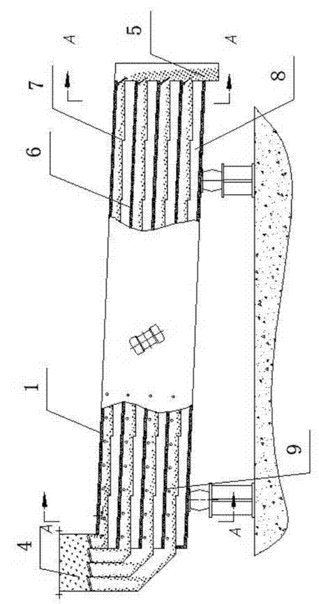
[0054] A vibrating laminar flow grain dryer, which consists of: a box body 1 with a shock absorption device, the box body 1 has a hot air inlet 2 and an air outlet 3, and the box has a heated The feeding port 4 and the discharging port 5 of the grain, the box body is equipped with a vibrating material bed 6, and the upper part of the vibrating material bed is the material chamber 7, and the heating chamber 8 is below. The opening is in communication with the material chamber, and the hot air inlet and outlet are in communication with the heating chamber.

[0055] After the heated grain enters the vibrating material bed 6 from the feed inlet 4, the vibrating material bed will convey the heated grain to the direction of the discharge port. During the conveying process, the heated grain will be heated and turned over by the vibrating material bed, so that the heated grain will be evenly combined with each other. The heating body is in contact with the vibrating material bed to eva...

Embodiment 2

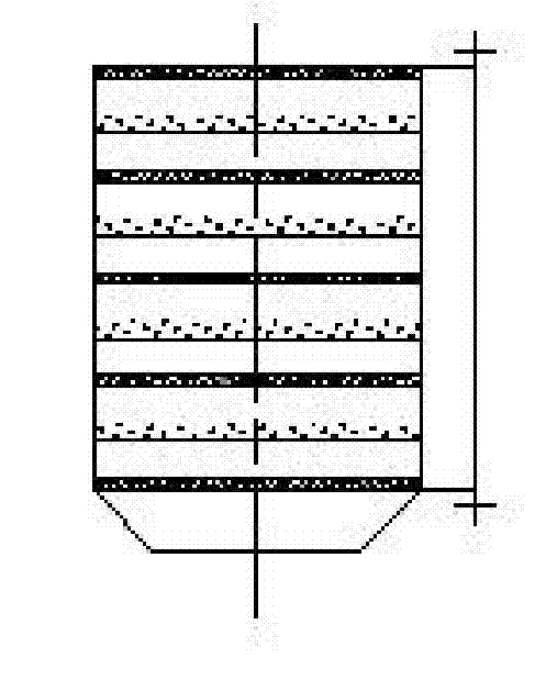
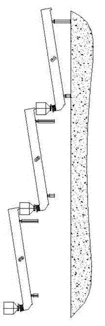
[0057] In the vibrating laminar flow grain dryer described in embodiment 1, the vibrating material bed has 1-15 layers, with 5-10 layers being more common, and a gas barrier 9 is installed between the vibrating material beds. , Divide the vibrating material bed into two unconnected spaces, the material chamber and the heating chamber. The heated and dried grain flows in the material chamber, and the heating gas flows in the heating chamber. The height of the material chamber and the heating chamber is generally about 10 cm. The height of 5 cm where the moisture is large is not less than 20 cm. In special cases, it is generally not more than 35 cm.

Embodiment 3

[0059] Embodiment 2 In the vibrating laminar flow grain dryer, the air baffle is equipped with a flow baffle 10, which is in contact with the vibrating material bed at the height of the baffle, and the gas path is regulated into a circuitous The curve makes the heating more balanced. The length of the flow baffle is not less than 60% of the width of the material bed where the baffle is located, and the flow baffle is provided with spoiler holes to avoid dead ends. The length of the vibrating material bed is more than 2 meters. The gas barrier has a far-infrared coating on the side facing the grain, and the far-infrared coating is located on the side of the discharge port.

[0060] The air barrier has a far-infrared coating on the side facing the grain, and when the temperature of the heating chamber 8 reaches the release temperature of the far-infrared material, the grain is heated by the far-infrared.


PUM


Abstract

The invention relates to an oscillating laminar-flow grain dryer. Currently, a vertical grain drying tower is commonly used for grain drying in the world. The heat source of the vertical grain drying tower is coal, fuel oil, burning rice husks or straws generally; a burning material combusts in a hot-blast stove and generates hot wind, then grains are added, and the hot wind is introduced into the drying tower to evaporate moisture so as to reduce moisture in the grains. The oscillating laminar-flow grain dryer provided by the invention comprises a box (1) equipped with a damping device; the box is provided with a hot wind inlet (2), an air outlet (3), a feed inlet (4) and a discharge outlet (5), an oscillating material bed (6) is arranged in the box, a material chamber (7) is arranged above the oscillating material bed, a heating chamber (8) is arranged below the oscillating material bed, the feed inlet and the discharge outlet are communicated with the material chamber, and the hot wind inlet and the air outlet are communicated with the heating chamber. The oscillating laminar-flow grain dryer provided by the invention is used for grain drying.

Description

Technical field [0001] The present invention involves a drying equipment, especially the drying grain with vibration beds and the equipment of the bulk granules. Background technique [0002] Food is a necessity of human life, and countries attach great importance to food production and reserves.The natural moisture of newly harvested food is generally about 17%-32%, and the safe moisture of food storage is about 13%. Therefore, if you need to save food safely, you must give the food precipitation to safe water to store. [0003] At present, the world of grain drying is the use of vertical grain drying tower.The heat source generally comes from coal, fuel, rice -burning shells, and straw. The fuel is burned through the hot air furnace to generate hot air. After investing in the food, the hot air is connected into the drying tower to evaporate the moisture and reduce the moisture in the grain. [0004] There are many disadvantages of this drying method: [0005] 1. After the fuel ...

Claims


Application Information

Patent Timeline
Patent Type & Authority Applications(China)
IPC IPC(8): A23B9/08F26B17/00F26B25/00
Inventor 刘廷瑜
Owner HARBIN BEICANG GRAIN STORAGE PROJECT & EQUIP
Why Eureka
Try Eureka