Two-stage sludge drying method for energy saving and environmental protection

A technology of sludge drying, energy saving and environmental protection, applied in the direction of dehydration/drying/concentrated sludge treatment, etc., can solve the problems of difficulty in generalization, non-environmental protection, large investment in equipment, etc., and achieve flexible product use and less secondary pollution , the effect of low investment

Active Publication Date: 2015-09-09
NAVY MEDICINE RES INST OF PLA
View PDF3 Cites 0 Cited by
  • Summary
  • Abstract
  • Description
  • Claims
  • Application Information

AI Technical Summary

Problems solved by technology

Therefore, it is possible to have some individual examples under specific conditions in the market, but it is difficult to say that general promotion
A notable defect that the above-mentioned method exists is that it is not environmentally friendly, and the investment in equipment is large.

Method used


Image

  • Two-stage sludge drying method for energy saving and environmental protection

Examples


Embodiment 1

[0024] The weight moisture content of the dewatered sludge of the sewage plant is 80%, and the specific gravity is 660kg / m 3 , the weight content of organic matter (VS) is 61%, and the lower calorific value is 500kJ kg -1 ;

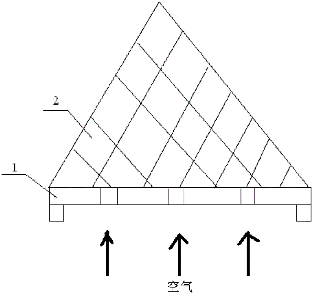
[0025] see figure 1 , the method of the present invention, comprises the steps:

[0026] (1) Add the additive to the dewatered sludge of the sewage plant, and pile it into a pile 2, which is placed on the ventilation frame 1. The thickness of the pile is 1 meter, and the air is introduced from the lower part of the ventilation frame. In the first 10 days, every 25 minutes , open air for 8 minutes; after 10 days: every 12 minutes, open air for 45 minutes;

[0027] Turn over once every 2 days, ventilation rate is 0.05(m 3 h -1 kg -1 ) conditions, after 20 days of biological flooding, a section of dewatered sludge was obtained;

[0028] The additive is selected from rice straw, and the added weight of the additive is 15% of the dewatered sludge of the...

Embodiment 2

[0033] The weight moisture content of the dewatered sludge of the sewage plant is 70%, and the specific gravity is 750kg / m 3 , the weight content of organic matter (VS) is 70%, and the lower calorific value is 760kJ·kg -1 ;

[0034] see figure 1 , the method of the present invention, comprises the steps:

[0035] (1) Add the additive to the dewatered sludge of the sewage plant, and pile it into a heap 2, which is mounted on the ventilation frame 1. The thickness of the pile is 2 meters, and the air is introduced from the lower part of the ventilation frame 1. In the first 10 days, every interval After 15 minutes, the air was injected for 12 minutes; after 10 days: every 8 minutes, the air was injected for 55 minutes;

[0036] Turn over once every 4 days, the ventilation rate is 0.1(m 3 h -1 kg -1 ) conditions, after 15 days of biological flooding, a section of dewatered sludge was obtained;

[0037] The additive is selected from a mixture of rice straw and sawdust, the ...


PUM

PropertyMeasurementUnit
thicknessaaaaaaaaaa
heating valueaaaaaaaaaa
particle diameteraaaaaaaaaa

Abstract

The present invention provides an energy-saving and environmental-friendly two-stage sludge drying method, comprising the steps of: (1) adding an additive to sludge dewatered in a wastewater treatment plant, stacking the sludge into stack body and putting on a ventilation holder, wherein the stack thickness is 1-2 meters, and feeding air from the bottom of the ventilation holder to obtain the first-grade dewatered sludge, wherein the additive is selected from the group consisting of one or more of straw or sawdust; (2) scattering a dewatering agent on the surface of the first-grade dewatered sludge stack body, wherein the thickness of the stack body is 20-30 cm, and standing overnight to obtain dry sludge. The dewatering agent is selected from the group consisting more than one of tricalcium silicate, dicalcium silicate, tricalcium aluminate or gypsum. The drying method has the advantages of low investment, low energy consumption, low operating cost, flexible product usage, etc. While the odor has less secondary pollution, the product is basically stable, no odor is released, the viscosity of sludge disappears, the sludge is conducive to storage, transportation and further processing.

Description

technical field [0001] The invention relates to a sludge drying method. Background technique [0002] In recent years, with the continuous expansion of urban sewage plants, the large amount of sludge produced is gradually becoming a worldwide problem. The moisture content of the sludge after dehydration is still as high as 80%. In order to be able to be landfilled or incinerated, further pretreatment is required to reduce the moisture content and meet the requirements of the next step of treatment. [0003] Currently, the conventional method is as follows: [0004] 1 Thermal drying: There are many methods on the market, such as rotary sleeve drying; vertical reflux drying; fluidized bed drying; blade drying machine; waste heat flue gas drying, etc. Removing moisture with thermal energy consumes a lot of energy, and in actual application, the investment is large and the operating cost is high. And the discharged waste gas has secondary pollution to the environment. Altho...

Claims


Application Information

Patent Timeline
Patent Type & Authority Patents(China)
IPC IPC(8): C02F11/12
Inventor 方晶晶刘虹傅吉尧徐新宏许林军肖存杰鲁毅钧方博杰
Owner NAVY MEDICINE RES INST OF PLA
Why Eureka
Try Eureka