
Isothermal sintering process of iron ore powder

A technology for iron ore powder and thermal sintering, which is applied in the field of iron ore powder sintering, can solve the problems of deterioration of thermal permeability of material layers, deterioration of sintering production process conditions, and decline of yield, etc., so as to prevent physical quality deterioration and improve excess heat. The effect of moving down and improving heat exchange efficiency

Active Publication Date: 2013-01-30
山东德钧精工机械有限公司
View PDF7 Cites 16 Cited by
  • Summary
  • Abstract
  • Description
  • Claims
  • Application Information

AI Technical Summary

Problems solved by technology

[0005]1. The thickness of the material layer increases, the automatic heat storage effect of sintering is further strengthened, the heat in the lower part of the material layer is excessive, and the thermal gas permeability of the material layer deteriorates, which makes the resistance of the sintered material layer increase, the vertical sintering speed decreases, the reducing atmosphere in the sintering process increases, and the quality of local sinters deteriorates due to high temperature over-melting
[0006]2. After the material layer is thickened, the amount of solid fuel is relatively reduced, and the sintered upper material layer is insufficient in heat, which leads to the deterioration of the strength of the sintered ore, the decrease of the yield rate, and the sintering of the finished product. Inhomogeneity of the ore, increase of powder return rate in the production system, deterioration of sintering production process conditions
[0008]At present, in order to take into account the low-temperature sintering technology of thick material layer, the amount of water added is selected at the middle value required by the two places, and this choice makes the sintered ore Finished product quality is also greatly affected

Method used


Image

  • Isothermal sintering process of iron ore powder

Examples


specific Embodiment approach

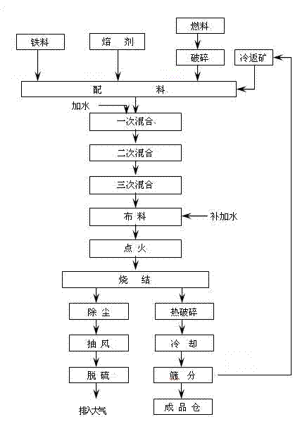
[0025] Specific implementation methods: such as figure 1 As shown, a soaking sintering process of iron ore powder, the process includes mixing, distributing, igniting, ventilating sintering, cooling, sizing, and making finished sintered ore. The present invention focuses on improving the material distribution stage, and adopts a small amount of water distribution in the mixing process of the middle and upper parts of the material layer of the sintering machine trolley. The moisture of the original water distribution is 6.0%. Afterwards, a small amount of water is added in the sintering machine using an atomizing spray device in the material distribution process, and the lower part of the material layer is also externally distributed to increase the moisture content of the lower part of the material layer to 7.0%.

[0026] Specific atomization and spraying method: after the mixture reaches the set distribution height during the distribution process, an atomization and spraying...


PUM


Abstract

The invention, relating to the field of iron ore powder sintering in metallurgy production system, particularly discloses an isothermal sintering process of iron ore powder, comprising uniformly mixing, distributing materials, igniting, sintering by air draft, cooling, and granulating to obtain a finished agglomerate, wherein in the step of distributing materials of a sintering machine, an atomization spray device is used for adding water to the sintering mixture; small water addition is adopted in material distribution of the middle and upper portion of the mixture material layer on the sintering machine, the water content is 6-6.5%; the water content of the lower portion of the material layer is raised by 1.0-2.0%, thus the water content reaches 7-8.5%. According to the invention, under the condition of applying thick material layer sintering technology, the water contents of the middle and lower portions of the sintering material layer are properly raised, the heat exchange efficiency of the sintering material layer is raised, the hot permeability deterioration at different height positions of the mixture in the sintering process is improved, the agglomerate quality deterioration is effectively avoided, the yield and quality of the agglomerate are raised, and the sintering solid burn-up is reduced.

Description

technical field [0001] The invention relates to the field of iron ore powder sintering in metallurgical production systems, in particular to an iron ore powder soaking sintering technology. Background technique [0002] Iron ore powder sintering is a block making process to provide high-quality iron-containing raw materials for blast furnace ironmaking. During production, CO, CO 2 , NO, SO 2 Greenhouse gas emissions account for about 10% of the iron and steel industry, and reducing greenhouse gas emissions in sintering waste gas has become an urgent problem to be solved in my country's environmental protection. In the current sintering production, the low-temperature sintering process with a thick material layer is a technology widely used in recent years. The principle is to increase the thickness of the material layer and use the upper layer The automatic heat storage share provided by the sintered ore improves the quality and output of the sintered ore and reduces the ...

Claims


Application Information

Patent Timeline
IPC IPC(8): C22B1/16
Inventor 李兴文杨延超宋亚男陈虎
Owner 山东德钧精工机械有限公司
Learn More