Feedforward radar antenna

A radar antenna and antenna technology, applied in the direction of antennas, electrical components, etc., to achieve the effect of improving the deflection problem, saving space, and good directionality

Active Publication Date: 2013-01-30
KUANG CHI INST OF ADVANCED TECH +1
View PDF4 Cites 8 Cited by
  • Summary
  • Abstract
  • Description
  • Claims
  • Application Information

AI Technical Summary

Problems solved by technology

[0004] The purpose of the present invention is to solve the problem of manufacturing parabolic reflectors in the prior art, and provide a feed-forward radar antenna. The antenna adopts a flat metamaterial, which saves the space of the antenna, improves the deflection problem of electromagnetic wave incident at a large angle, and improves the The efficiency of energy radiation; at the same time, it also improves the front-to-back ratio of the antenna, making the antenna's directivity better, and also solves the difficulty of avoiding the manufacture of high-precision parabolic reflectors

Method used


Image

  • Feedforward radar antenna
  • Feedforward radar antenna
  • Feedforward radar antenna

Examples


Embodiment Construction

[0029] The present invention will be described in further detail below in conjunction with the embodiments and the accompanying drawings, but the embodiments of the present invention are not limited thereto.

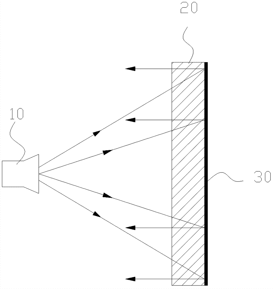
[0030] figure 2 It is a schematic structural view of the feedforward radar antenna of the present invention, the antenna includes a feed source 10, a metamaterial panel 20, and a reflector 30, and the feed source 10 and the emitter panel 30 are respectively located on both sides of the metamaterial panel 20, reflecting The plate 30 is closely connected to the metamaterial panel 20 .

[0031] Usually, the electromagnetic wave radiated from the feed source 10 is a spherical electromagnetic wave, but the far-field direction performance of the spherical electromagnetic wave is not good, and there are great limitations for long-distance signal transmission using the spherical electromagnetic wave as a carrier, and the attenuation is fast. A metamaterial panel 20 with electr...


PUM


Abstract

The invention relates to a feedforward radar antenna. The antenna comprises a feed source and a metamaterial panel. The antenna also comprises a reflecting plate clinging to one side of the metamaterial panel, wherein the metamaterial panel comprises a plurality of core layers with the same refractive index distribution; each core layer comprises a plurality of metamaterial units; each metamaterial unit comprises a unit substrate with one or more holes; the refractive indexes of the core layers of the metamaterial panel are circularly distributed, with own centers as the centers of circles; the refractive index gradually decreases with increase of the radius; and the refractive indexes in positions with the same radius are the same. The feedforward radar antenna has the following beneficial effects: by designing the distribution law of the refractive indexes inside the metamaterial panel, the deflection of large-angle incidence of electromagnetic waves is improved, and the energy radiation efficiency is improved; meanwhile, the front-to-back ratio of the antenna is increased, and the directivity of the antenna becomes better; and as the antenna adopts the flat metamaterial, the space of the antenna is saved.

Description

technical field [0001] The invention relates to the field of radar antennas, and more specifically, to a feedforward radar antenna using metamaterials. Background technique [0002] Such as figure 1 As shown, the feedforward parabolic antenna includes a feed source 1, a main reflector 2 and a bracket 3, the feed 1 is installed at the focal point of the main reflector 2, and the mouth surface of the feed source 1 and the mouth surface of the main reflector 2 On the contrary, the electromagnetic waves reflected by the main reflecting surface 2 are concentrated into the feed source. The advantage of the feedforward parabolic antenna is that the feed source has little shielding of electromagnetic waves in the air, the structure is simple, the cost is low, and the installation and debugging are easy. The tuner is located at the focal point of the parabola, and sunlight is sometimes focused on the tuner, which increases the temperature of the tuner, reduces the signal-to-noise r...

Claims


Application Information

Patent Timeline
Patent Type & Authority Applications(China)
IPC IPC(8): H01Q15/00H01Q15/23H01Q19/06H01Q19/10
Inventor 刘若鹏季春霖岳玉涛郭洁
Owner KUANG CHI INST OF ADVANCED TECH
Why Eureka
Try Eureka