

Cable shielding layer splicing method
A cable shielding layer and shielding layer technology, applied in the direction of circuits, connections, electrical components, etc., can solve the problems of shielding layer oxidation, long heating time, unreliable contact of the shielding layer, etc., to ensure the quality of connection, reliable contact, To ensure the effect of low resistance value requirements
- Summary
- Abstract
- Description
- Claims
- Application Information
AI Technical Summary
Problems solved by technology
Method used
Image

Examples
Embodiment Construction
[0023] A cable shielding layer connection method provided by the present invention will be introduced below in conjunction with the accompanying drawings and embodiments: the method includes the following steps
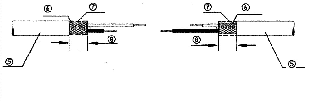
[0024] 1. Clean the shielding layers of the two connected cables
[0025] Clean the shielding layers of the two connected cables with medical absorbent cotton soaked in absolute ethanol.
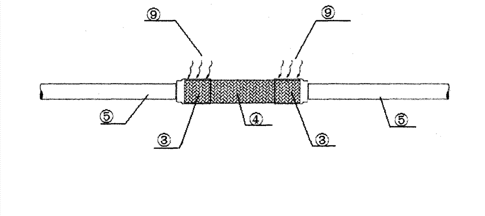
[0026] 2. Carry out tinning on the welding parts of the shielding layers of the two consecutive cables
[0027] Use temperature-controlled electric chromium ferrochrome to carry out tinning treatment on the continuous connection parts of the shielding layers of the two cables that need to be connected (ie: the welding part with the shielding net sleeve). figure 2 As shown, the tinning length (the solder ring at both ends of the shielding net sleeve and the tinned part of the cable shielding layer) L = 10mm ~ 12mm, the tin-lead solder adopts GB / T3131HLSn60PbA, the tinning temperatu...
PUM
| Property | Measurement | Unit |
|---|---|---|
| Length | aaaaa | aaaaa |
Abstract
Description
Claims
Application Information