
Dc-dc converter and voltage conversion method thereof

A DC-to-DC converter technology, applied in the direction of converting DC power input to DC power output, high-efficiency power electronic conversion, output power conversion device, etc., can solve problems such as noise interference and affecting the quality of electronic products

Active Publication Date: 2013-01-30
UPI SEMICON CORP
View PDF3 Cites 2 Cited by
  • Summary
  • Abstract
  • Description
  • Claims
  • Application Information

AI Technical Summary

Problems solved by technology

In this way, there will be noise interference when users use various electronic products (such as mobile phones, computers, or walkmans) using constant on-time regulators, which will affect the quality of electronic products.

Method used


Image

  • Dc-dc converter and voltage conversion method thereof
  • Dc-dc converter and voltage conversion method thereof
  • Dc-dc converter and voltage conversion method thereof

Examples


Embodiment Construction

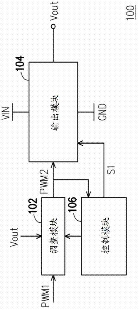
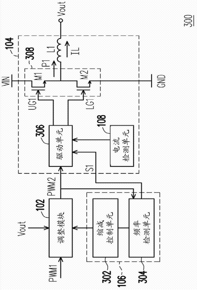
[0064] figure 1 It is a schematic diagram of a DC-DC converter according to an embodiment of the present invention. Please refer to figure 1 , the DC-DC converter 100 includes an adjustment module 102 , an output module 104 and a control module 106 . The adjustment module 102 is coupled to the output module 104 and the control module 106 , and the control module 106 is also coupled to the output module 104 . The output module 104 is coupled to the ground voltage GND, the input voltage VIN of the DC-DC converter 100 and the control module 106 .

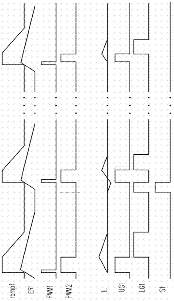
[0065] The adjustment module 102 is used to receive the first pulse width modulation signal PWM1 and the output voltage Vout of the DC-DC converter 100, and output a second pulse width with a constant on-time according to the first pulse width modulation signal PWM1 and the output voltage Vout modulation signal PWM2. figure 2 It is a schematic diagram of waveforms of multiple signals in the DC-to-DC converter of the embodiment of ...


PUM


Abstract

The invention provides a DC-DC converter and a voltage conversion method thereof. When a load of the DC-DC converter is too light, the DC-DC converter can raise a frequency of its PWM signal, and reduce a pulse width of the PWM signal, so as to avoid the frequency of the PWM signal falling into a frequency range that can heard by human's ear and maintain high conversion efficiency of the DC-DC converter.

Description

technical field [0001] The present invention relates to a DC-to-DC converter, and in particular to a DC-to-DC converter capable of adjusting the pulse width of a pulse width modulation signal and a voltage conversion method thereof. Background technique [0002] As we all know, the operating voltages used by the central processing unit (CPU), dynamic random access memory (DRAM), graphics chip (graphic chip), and chip set (chip set) in the computer system are all different. Therefore, the computer system needs Many DC-to-DC converters are used to convert the DC input voltage (for example, 19V) provided by the power supply into the operating voltage required by each component. A Constant On Time (COT) regulator is a DC-to-DC converter. Generally speaking, when the feedback voltage is lower than the reference voltage, the constant on-time regulator can turn on a main switch for a fixed period and adjust the non-conduction period of the main switch to provide a stable output vo...

Claims


Application Information

Patent Timeline
Patent Type & Authority Applications(China)
IPC IPC(8): H02M3/156
CPCY02B70/16H02M2001/0032H02M1/44H02M3/156H02M2001/0025Y02B70/10H02M1/0025H02M1/0032
Inventor 黄华强
Owner UPI SEMICON CORP
Learn More