
An automatic optical detection laser welding system

An automatic optical detection and laser welding technology, applied in laser welding equipment, welding equipment, metal processing equipment, etc., can solve problems such as eye fatigue, easy corrosion of PCB board surface, continuous welding, etc., to improve work efficiency and reduce defects. phenomenon, the effect of reducing the vulnerability

Inactive Publication Date: 2015-09-16
武汉市楚源光电有限公司
View PDF4 Cites 0 Cited by
  • Summary
  • Abstract
  • Description
  • Claims
  • Application Information

AI Technical Summary

Problems solved by technology

However, manual inspection is adopted. For boards with many points or large batches, human eyes will be fatigued due to long-term inspection, resulting in missed inspections; moreover, PCB boards are soldered by wave soldering and reflow soldering processes, which are easy to corrode PCBs. The surface of the board may cause some components on the PCB to be damaged and fail under large-scale high-temperature conditions, resulting in difficulties in repairing the PCB board. Poor; In addition, after wave soldering and reflow soldering, there will be a lot of residue on the board surface, which is easy to stain the PCB board and affect the cleanliness of the PCB board

Method used


Image

  • An automatic optical detection laser welding system

Examples


Embodiment Construction

[0014] The present invention will be described in further detail below in conjunction with the embodiments in the accompanying drawings, but this does not constitute any limitation to the present invention.

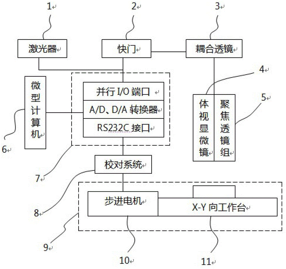
[0015] refer to figure 1 Shown is a schematic block diagram of the automatic optical inspection laser welding system of the present invention, the system is composed of an automatic optical inspection system (AOI system) and a laser welding system, wherein the automatic optical inspection system includes a microcomputer 6, a graphic sampling system ( Including shutter 2 and stereo microscope 4), data conversion system 7, proofreading system 8 and automatic workbench 9, the laser welding system includes laser 1, coupling lens 3 and focusing lens group 5. In this embodiment, the system uses a fiber laser with a wavelength of 980nm or 808nm.

[0016] The data conversion system 7 is loaded in the microcomputer 6, and between it and the microcomputer 6, various calculation pr...


PUM

PropertyMeasurementUnit
wavelengthaaaaaaaaaa

Abstract

The invention discloses an automatic optical detection laser welding system which is composed of an automatic optical detection system and a laser welding system. The automatic optical detection system comprises a microcomputer, a graph sampling system, a data conversion system, a revision system and an automatic working platform; and the laser welding system comprises a laser, a coupling lens and a focusing lens assembly. The automatic optical detection system is integrated with the laser welding system, and bugs in the printed circuit board (PCB) welding and detection process are reduced by matching the high-automation high-accurate automatic optical detection system with the laser welding technology which is small in influenced area and high in energy concentration. Therefore, working efficiency is improved, multiple undesirable phenomena during welding are reduced, the welding devices are ensured to be free of damage during welding, and simultaneously detection speed, efficiency and stability are ensured.

Description

technical field [0001] The present invention relates to a welding system, more specifically, to an automatic optical detection laser welding system. Background technique [0002] At this stage, various PCB manufacturers inspect the soldering status of printed circuit boards after wave soldering and reflow soldering, basically by visual inspection, which can be flexibly judged according to standards to determine the qualified rate of PCB boards after soldering. However, manual inspection is adopted. For boards with many points or large batches, human eyes will be fatigued due to long-term inspection, resulting in missed inspections; moreover, PCB boards are soldered by wave soldering and reflow soldering processes, which are easy to corrode PCBs. The surface of the board may cause some components on the PCB to be damaged and fail under large-scale high-temperature conditions, resulting in difficulties in repairing the PCB board. Poor; In addition, after wave soldering and re...

Claims


Application Information

Patent Timeline
Patent Type & Authority Patents(China)
IPC IPC(8): B23K26/21B23K26/03B23K26/70
Inventor 胡骁闻靖
Owner 武汉市楚源光电有限公司
Learn More