Wire fusing method of laser liquid filling welding

A liquid filling and laser technology, applied in laser welding equipment, welding equipment, metal processing equipment, etc., can solve the problems of poor weld quality, poor melting stability, and low welding efficiency, and achieve faster droplet transfer frequency and joint deformation The effect of small amount and lower wire feeding accuracy

Active Publication Date: 2015-03-04
HARBIN INST OF TECH
View PDF8 Cites 0 Cited by
  • Summary
  • Abstract
  • Description
  • Claims
  • Application Information

AI Technical Summary

Problems solved by technology

[0007] The present invention aims to solve the problems of poor melting stability of the welding wire in the welding process, strict requirements on wire feeding accuracy, low welding efficiency and poor weld quality in the existing laser wire filling welding fusion method, and proposes a laser liquid filling welding method. The fuse method

Method used


Image

  • Wire fusing method of laser liquid filling welding
  • Wire fusing method of laser liquid filling welding
  • Wire fusing method of laser liquid filling welding

Examples


specific Embodiment approach 1

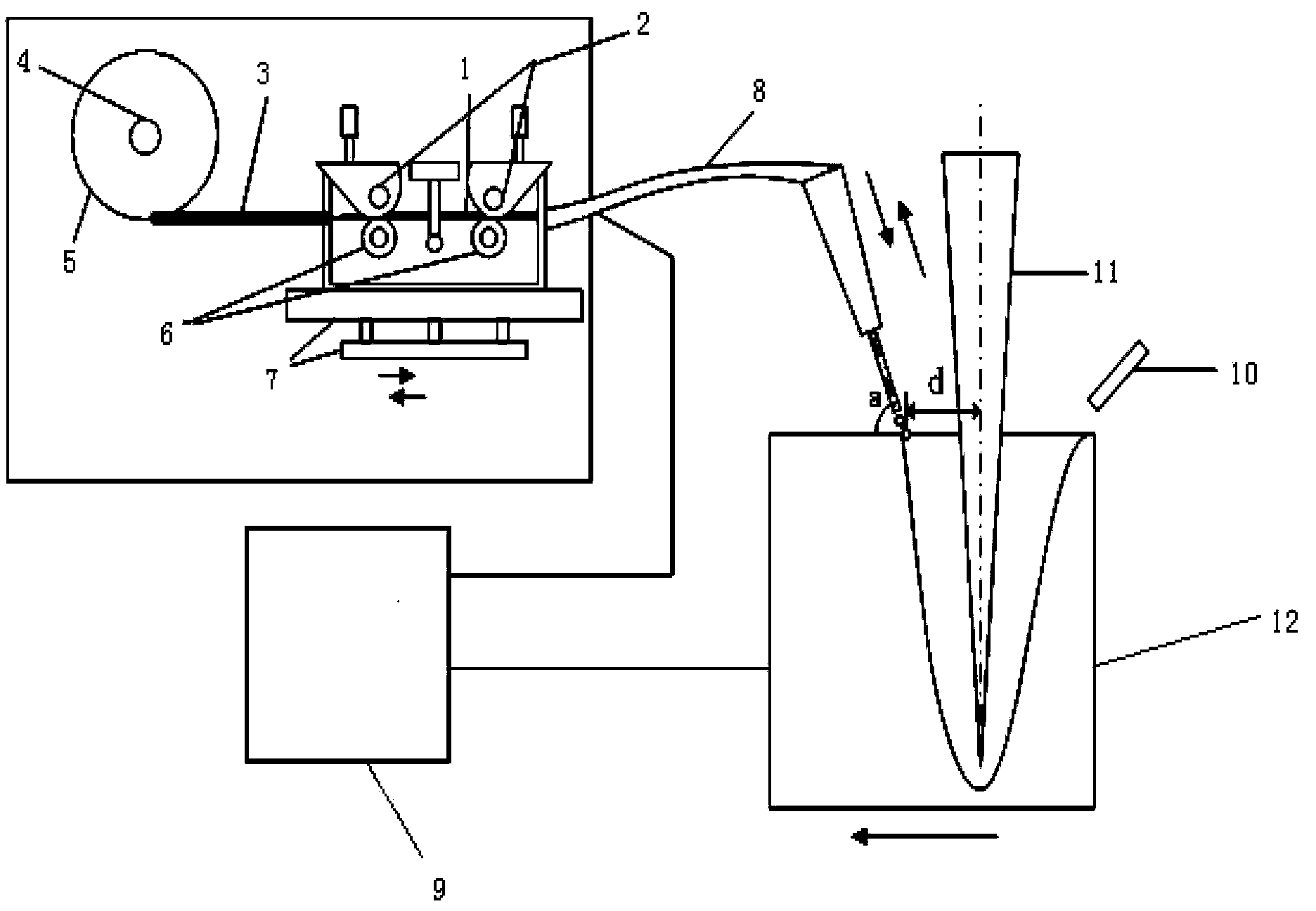
[0022] Specific embodiment one: a kind of fuse method of laser liquid filling welding in this embodiment is carried out according to the following steps:

[0023] 1. Connect the MIG welding torch to the vibrating wire feeding device. One pole of the TIG power supply is connected to the MIG welding torch, and the other pole is connected to the base material. The TIG power supply adopts the current output form of DC positive connection, DC reverse connection or AC;

[0024] 2. Start the laser to form a molten pool on the base material, and the input type of the laser is continuous output or pulse output;

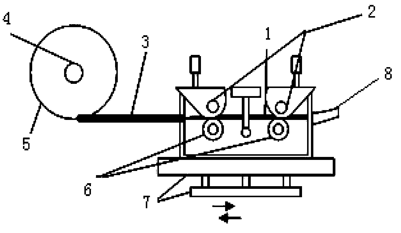
[0025] 3. Ignite the auxiliary arc to heat the welding wire, and start the wire feeding device and the vibration device at the same time to ensure that the welding wire continues to melt under the action of the arc and continue to feed under the vibration state, wherein the wire feeding device is connected to the MIG welding torch;

[0026] 4. The droplet grows up gradually. W...

specific Embodiment approach 2

[0034] Specific embodiment 2: The difference between this embodiment and specific embodiment 1 is that the current of the TIG power source described in step 1 is 1A to 90A, and the arc striking method is high-frequency arc striking. arc, premelting the welding wire in front of the laser. Other steps and parameters are the same as those in Embodiment 1.

specific Embodiment approach 3

[0035] Embodiment 3: This embodiment differs from Embodiment 2 in that the current of the TIG power supply in step 1 is 5A-80A. Other steps and parameters are the same as in the second embodiment.


PUM

PropertyMeasurementUnit
diameteraaaaaaaaaa
diameteraaaaaaaaaa

Abstract

The invention discloses a wire fusing method of laser liquid filling welding. The wire fusing method aims at solving the problem that during welding of the welding wire, the existing laser wire fusing method of laser wire filling welding is poor in melting stability, rigid in wire feeding accuracy requirements, low in welding efficiency and poor in welding quality. The wire fusing method of the laser liquid filling welding comprises the following steps: 1, connecting a metal-insert gas welding (MIG) gun with a vibration wire feeding device, connecting a pole of a tungsten-arc welding (TIG) power source with the MIG gun, and connecting the other pole of the TIG power source with a base metal; 2, starting a laser, and enabling laser to form a molten pool on the base metal; 3, heating the welding wire with auxiliary electric arc, and simultaneously starting the wire feeding device and a vibration device; and 4, enabling molten drops to grow bigger gradually and to be transited to the molten pool in fine particle mode by overcoming surface tension under the assisting effect of mechanical vibration force, weight and the like. The wire fusing method of the laser liquid filling welding can be applied to the field of metal laser liquid filling welding connection engineering.

Description

technical field [0001] The invention relates to a fuse method for laser liquid filling welding. Background technique [0002] Laser welding has many unparalleled advantages compared to traditional welding methods, but laser self-fluxing welding still has many limitations, such as strict requirements on the joint gap, the maximum allowable gap is no more than 10% of the plate thickness, and the chemical properties of the weld cannot be changed. Composition, etc., so in many cases the laser wire filler welding process must be used. Studies have shown that laser filler wire welding can not only improve the adaptability of the gap, change the alloy composition of the weld, but also improve the energy coupling between the laser and the workpiece. Compared with laser self-fusion welding, the weld surface formed by laser filler wire welding is smoother and more uniform, especially when welding aluminum alloys. [0003] Laser wire-filled welding can well solve the limitation of jo...

Claims


Application Information

Patent Timeline
Patent Type & Authority Patents(China)
IPC IPC(8): B23K26/348
Inventor 李俐群陈彦宾彭进
Owner HARBIN INST OF TECH
Why Eureka
Try Eureka