Grinding component for steam trap in nuclear power plant

A technology for steam traps and nuclear power plants, which is applied in the field of grinding components of steam traps in nuclear power plants. It can solve problems such as uneven grinding force, time-consuming, and deformation of sealing planes, and achieve the effects of simple installation and disassembly, saving working time and saving human resources.

Inactive Publication Date: 2013-02-13
CLP CHINA NUCLEAR POWER ENG TECH
View PDF0 Cites 2 Cited by
  • Summary
  • Abstract
  • Description
  • Claims
  • Application Information

AI Technical Summary

Problems solved by technology

[0002] At present, nuclear power plants have always been troubled by the defect repair work of steam traps. Each sub-unit needs to be dismantled and overhauled for annual refueling and overhaul. However, almost all the dismantled equipment has defects of varying degrees, which seriously affects the safety and stability of the nuclear power plant system. operation, and the maintenance work of this type of steam trap has always been a job that makes the static machine scratch its head
The working principle of this type of steam trap is not complicated, but the structure is relatively special. When the sealing surface of the valve seat of the steam trap is defective, the grinding and repair work will bring certain difficulties. At present, it can only be carried out by relying on the old-fashioned grinding mold processed by the machine tool itself. Manual grinding, this grinding method is time-consuming, laborious and has many unstable factors, because this type of steam trap is divided into vertical installation and horizontal installation, and the valve seat of this equipment does not have a suitable grinding fixed position during the grinding process, so It also brings difficulties to the grinding and repairing work. Even if the grinding effect is not satisfactory after manual grinding and repairing, there have been many times in the history that the grinding force is uneven, resulting in serious deformation of the entire sealing plane. The equipment is damaged and the steam trap must be replaced.

Method used


Image

  • Grinding component for steam trap in nuclear power plant

Examples


Embodiment

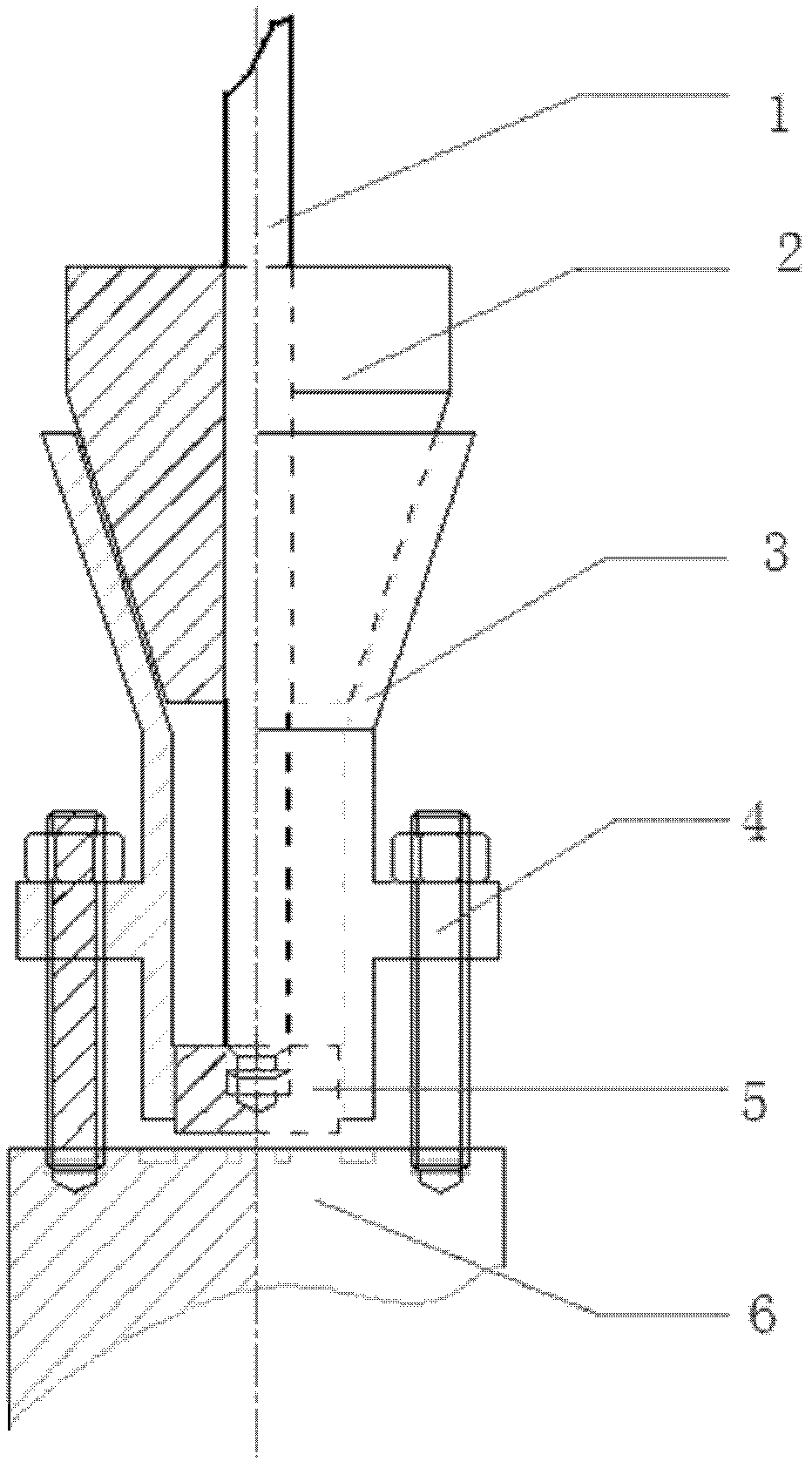
[0018] Such as figure 1 As shown, a nuclear power plant steam trap grinding assembly includes a fixed support device 3, a nylon centering sleeve 2, a grinding disc 5, a grinder grinding rod 1 and a bolt 4, and the upper part of the fixed support device 3 is in the shape of an inverted cone. The lower part is in the shape of a hollow cylinder, and the nylon centering sleeve 2 is in the shape of a funnel, and is arranged in the upper part of the inverted cone of the fixed support device 3. The grinding machine will have a certain degree of shaking and off-target phenomena during the grinding process, which is perfect The centering sleeve can play a decisive role in preventing the above phenomenon in the whole grinding. Nylon material has high mechanical strength, heat resistance, wear resistance, self-lubrication, shock absorption and noise reduction.

[0019] The grinding disc 5 is a brass grinding disc, which is arranged at the lower end of the hollow cylinder of the fixed su...


PUM


Abstract

The invention relates to a grinding component for a steam trap in a nuclear power plant. The grinding component comprises a fixed supporting device, a nylon centering sleeve, a grinding disk, a grinder grinding rod and bolts, wherein the fixed supporting device is connected with the steam trap through the bolts; the nylon centering sleeve is sleeved on the fixed supporting device; the grinding disk is arranged at the bottom of the fixed supporting device; and the grinder grinding rod penetrates through the nylon centering sleeve and is connected with the grinding disk. Compared with the prior art, the grinding component has the advantages of high efficiency and precision, convenience for machining and the like, and is simply dismounted and mounted.

Description

technical field [0001] The invention relates to a nuclear power steam trap, in particular to a nuclear power plant steam trap grinding assembly. Background technique [0002] At present, nuclear power plants have always been troubled by the defect repair work of steam traps. Each sub-unit needs to be dismantled and overhauled for annual refueling and overhaul. However, almost all the dismantled equipment has defects of varying degrees, which seriously affects the safety and stability of the nuclear power plant system. Operation, and the maintenance work of this type of steam trap has always been a job that makes the static machine scratch its head. The working principle of this type of steam trap is not complicated, but the structure is relatively special. When the sealing surface of the valve seat of the steam trap is defective, the grinding and repair work will bring certain difficulties. At present, it can only be carried out by relying on the old-fashioned grinding mold ...

Claims


Application Information

Patent Timeline
Patent Type & Authority Applications(China)
IPC IPC(8): B24B37/00B24B37/34
Inventor 亢凯鹏刘鑫许国彪
Owner CLP CHINA NUCLEAR POWER ENG TECH
Why Eureka
Try Eureka