Full rotation steering oar device installation method
An installation method and full-rotation technology, applied in transportation and packaging, ship parts, ships, etc., can solve the problems of high cost, difficulty and labor, and achieve the effect of improving work efficiency, reducing shipbuilding cost, and improving installation quality and work efficiency.
- Summary
- Abstract
- Description
- Claims
- Application Information
AI Technical Summary
Problems solved by technology
Method used
Image
Examples
Embodiment 1
[0040] Embodiment 1 is the installation method of the rudder and paddle device from top to bottom
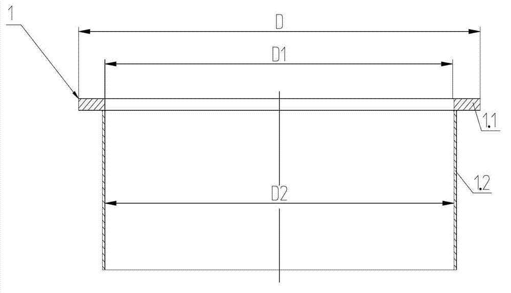
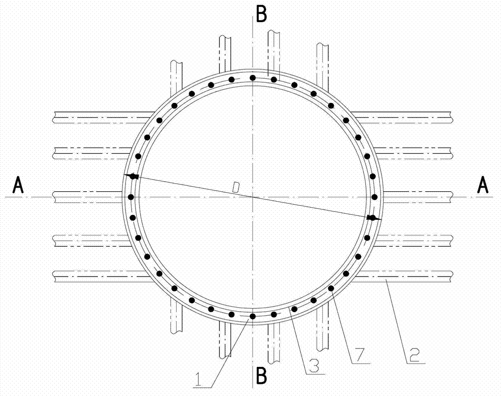
[0041] Such as figure 1 , 3 , 4, 6, and 7, a method for installing a full-turn rudder propeller device from top to bottom includes the following steps:
[0042] 1) Make casing flange 1, which includes base flange 1.1 and casing body 1.2, where the thickness of base flange 1.1 has a machining allowance of about 15mm, and the inner hole of base flange 1.1 is processed to finished size D1. The height of the casing 1.2 should reserve about 100mm from the lowest point of the bottom plate protruding from the casing for support and clamping during vertical lathe processing, and the excess part is cut off along the line of the bottom after reset;
[0043] 2) The intermediate bearing base near the rudder propeller base has been welded. For electric propulsion full-turn rudder propellers, the base of the propulsion motor has been welded. On this basis, the main body of the ship is bui...
Embodiment 2
[0057] Embodiment 2 is that the rudder and paddle device is installed from bottom to top
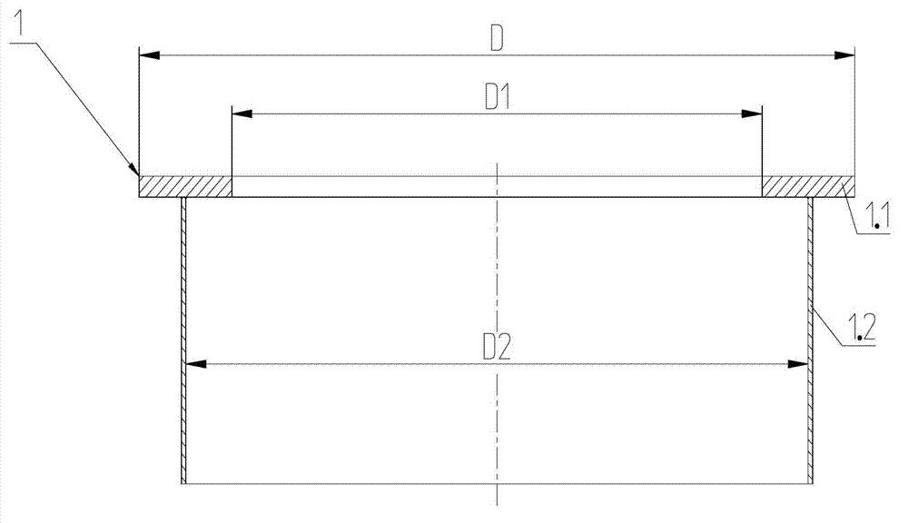
[0058] Such as figure 2 , 3 , 5, 8, and 9, a method for installing a full-turn rudder propeller device from bottom to top includes the following steps:
[0059] 1) Make casing flange 1, which includes base flange 1.1 and casing body 1.2, where the thickness of base flange 1.1 has a machining allowance of 15 mm, and the inner hole of base flange 1.1 is machined to Finished size D1. The height of the casing 1.2 of the casing should protrude about 100mm from the lowest point of the bottom plate of the casing, for support and clamping during vertical lathe processing, and the excess part is cut off along the line of the bottom of the ship after reset;
[0060] 2) The intermediate bearing base near the rudder propeller base has been welded. For electric propulsion full-turn rudder propellers, the base of the propulsion motor has been welded. On this basis, the main body of the ship is b...
Embodiment 3
[0075] Embodiment 3 is the installation method of rudder propeller unit assembly
[0076] Such as Figure 4 , Figure 5 The frustum cell design shown, corresponds to Figure 6 , Figure 8 The installation method of the rudder propeller shown. This process design provides favorable conditions for unit assembly. A method for assembling a full-turn rudder-propeller unit, the steps of which are as follows:
[0077] Step 1) ~ Step 9) are basically the same as Embodiment 1 and Embodiment 2, the difference is that in Step 9) the unit body of the conical table is finished, so that the installation mating surface, the groove of the sealing ring ( Figure 5 The installation mating surface of the lower surface of the conical platform unit body shown is not provided with a sealing ring groove) and all screw holes on the flange of the base meet the design requirements, and then the full-turn rudder propeller 5 is unit assembled with the conical platform unit body ;
[0078] 10) Build...
PUM
 Abstract
Description
Claims
Application Information
 - R&D
- Intellectual Property
- Life Sciences
- Materials
- Tech Scout
- Unparalleled Data Quality
- Higher Quality Content
- 60% Fewer Hallucinations
Browse by: Latest US Patents, China's latest patents, Technical Efficacy Thesaurus, Application Domain, Technology Topic, Popular Technical Reports.
© 2025 PatSnap. All rights reserved.Legal|Privacy policy|Modern Slavery Act Transparency Statement|Sitemap|About US| Contact US: help@patsnap.com


