[0019] In order to enable the examiners of the patent office, especially the public, to more clearly understand the technical essence and beneficial effects of the present invention, the applicant will describe in detail below by way of examples, but the descriptions of the examples are not intended to describe the solution of the present invention. Restriction, any equivalent transformation made according to the concept of the present invention is only formal but not substantive, and should be regarded as the scope of the technical solution of the present invention.
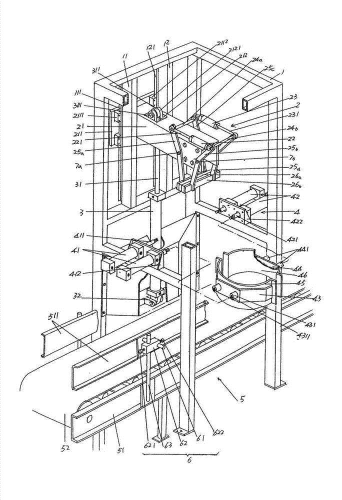
[0020] See figure 1 , a rack 1 in the form of a well-shaped frame used for construction is given. The rack 1 is configured in a complete set of automatic filling lines when in use. It is used for filling flexible packaging bags such as plastic film bags It is transported to the terminal part of the flexible packaging bag output mechanism 5 that is loaded into the packaging barrel at the barreling station. The flexible packaging bag output mechanism 5 is composed of a conveyor frame 51 and a conveyor belt 52. The conveyor belt 52 is driven by power to surround the length of the conveyor frame 51. The direction moves from one end to the other end of the conveying frame 51 repeatedly, that is to say, it forms a moving plane that moves repeatedly. Bag guard guides 511 are respectively provided on the upper sides of the two sides in the length direction of the conveying frame 51. The bag guard guides 511 protect and straighten the flexible packaging bag to avoid running out of the conveyor belt 52. The concept of straightening mentioned here refers to: Make the flexible packaging bag filled with material always in a vertical state with the bag mouth facing upwards. A set of guide plate adjustment devices 6 are arranged at intervals on both sides of the conveying frame 51 in the longitudinal direction. Each guide plate adjustment device 6 includes a fixed die rod 61 , an adjustment seat 62 and a fixed longitudinal rod 63 . On the outer side of the conveyor frame 51, the upper end of the fixed longitudinal rod 63 protrudes out of the edge of the conveyor belt 52, that is, stretches toward the top of the conveyor frame 51, and the adjustment seat 62 is arranged on the fixed longitudinal rod 63 to move up and down, and is equipped with There is a locking screw 621. After the position of the adjusting seat 62 on the fixing longitudinal rod 63 is determined, the adjusting seat 62 is locked on the fixing longitudinal rod 63 by the locking screw 621. One side is fixed, and the other end is slidably matched with the adjustment seat 62 . After the position of the adjustment seat 62 on the fixed crossbar 61 is determined, it is locked with the locking screw 622 . It can be seen from this that the bag guard guides 511 can be adjusted up and down as well as back and forth. When adjusting back and forth, the distance between a pair of bag guard guides 511 is changed to suit the diameter of the flexible packaging bag. time to adapt to the height change requirements of flexible packaging bags.
[0021] A first guide rail column 11 and a second guide rail column 12 are fixed on one side of the upper part of the above-mentioned rack 1 . A first guide rail 111 is fixed to one side in the height direction, and a second guide rail 121 is fixed to one side of the height direction of the second guide rail column 12 . Preferably, the cross-sectional shape of the first and second guide rails 111 and 121 is a dovetail shape. In addition, the first and second guide rails 111 and 121 can also be directly formed on the first and second guide rail uprights 11 and 12 respectively.
[0022] The preferred but not absolutely limited structure of the bag mouth clamping mechanism 2 is as follows: including a sliding beam 21, first and second bag clamping action cylinders 22, 23, first and second connecting shafts 24a, 24b, first and second connection shafts 24a, 24b, , the second, third and fourth clamping arms 25a, 25b, 25c, 25d, the first clamping flap 26a and the second clamping flap 26b, the cross-sectional shape of the sliding beam 21 is the n-shape of the English letter, that is, the inverted U One end of the sliding beam 21 facing the first and second guide rail columns 11 and 12 corresponds to between the first and second guide rail columns 11 and 12, and a sliding beam seat 211 is fixed at this end. One end of 211 is fixed with a pair of first rail sliders 2111 corresponding up and down. The pair of first rail sliders 2111 corresponds to the first rail 111 and is slidably matched with the first rail 111, and the other end of the sliding beam seat 211 A pair of second rail sliders 2112 corresponding to the upper and lower sides are fixed at positions corresponding to the second rails 121 , and the pair of second rail sliders 2112 are slidably matched with the second rails 121 . As mentioned above, since the cross-sectional shapes of the first and second guide rails 111 and 121 are dovetail-shaped, the cross-sectional shapes of the guide-slider grooves on the first and second guide-rail blocks 2111 and 2112 are also dovetail-shaped. The other end of the aforementioned sliding beam 21 is configured as a horizontal cantilevered end. The first clamp arm 25a and the second clamp arm 25b are located on one side of the horizontal cantilever end of the sliding beam 21, and the middle part of the first clamp arm 25a in the height direction is connected to the side of the horizontal cantilever end by the first pin 7a. The middle part in the height direction of the second clamping arm 25b is pivotally connected with the one side of the horizontal cantilever end by the second pin 7b. The third clamping arm 25c and the fourth clamping arm 25d are located on the other side of the aforementioned horizontal cantilever end of the sliding beam 21, and the middle portion of the third clamping arm 25c in the height direction is pivotally connected to the aforementioned first pin shaft 7a, And the middle part of the fourth clamping arm 25d in the height direction is pivotally connected with the aforementioned second pin shaft 7b. It can be seen that the first clamping arm 25a is pivotally connected to one end of the first pin shaft 7a, the third clamping arm 25c is pivotally connected to the other end of the first pin shaft 7a; the second clamping arm 25b is pivotally connected to one end of the second pin shaft 7b The fourth clamping arm 25d is pivotally connected to the other end of the second pin shaft 7b. As shown in the figure, the first and second clamping arms 25a, 25c are kept corresponding to one side and the other side of the horizontal cantilever end of the sliding beam 21. Similarly, the second and fourth clamping arms 25b, 25d are on the horizontal cantilever end. One side and the other side correspond to each other. One end of the first connecting shaft 24a is connected with the upper end of the first clamping arm 25a, and the other end of the first connecting shaft 24a is connected with the upper end of the third clamping arm 25c. One end of the second connecting shaft 24b is connected with the upper end of the second clamping arm 25b, and the other end of the second connecting shaft 24b is connected with the upper end of the fourth clamping arm 25d. The tail of the cylinder body of the first bag clamping action cylinder 22 is connected to the aforementioned end of the second connecting shaft 24b, and the first bag clamping action cylinder column 221 of the first bag clamping action cylinder 22 is connected to the aforementioned end of the first connection shaft 24a. connect. The tail of the cylinder body of the second bag clamping action cylinder 23 is connected to the other end of the first connecting shaft 24a, and the second bag clamping action cylinder column 231 of the second bag clamping action cylinder 23 is connected to the second connection shaft 24b. The aforementioned other end is connected. It can be seen that the first and second bag clamping action cylinders 22 and 23 are arranged opposite to each other. One end of the first clamping flap 26a is fixed to the lower end of the first clamping arm 25a, and the other end is fixed to the lower end of the third clamping arm 25c. One end of the second clamping flap 26b is fixed to the lower end of the second clamping arm 25b, and the other end is fixed to the lower end of the fourth clamping arm 25d.
[0023] In this embodiment, the first bag clamping action cylinder 22 and the second bag clamping action cylinder 23 are both air cylinders. However, if oil cylinders are used, they should be regarded as equivalent replacements and still belong to the protection scope of the present invention. .
[0024] One end of the sliding beam 21 is provided with an escape hole 212 , and a cylinder column connecting lug 2121 is fixed to the hole walls on the two sides corresponding to the escape hole 212 , that is to say, the cylinder column connecting lug 2121 has a pair of .
[0025] please continue to see figure 1 , a lifting action cylinder 3 is given, the lifting action cylinder 3 is fixed on the aforementioned frame 1 in a longitudinal state, specifically: connecting the cylinder tail of the lifting action cylinder 3 with the cylinder base 32, and the cylinder base 32 is preferably It is fixed on the frame 1 by welding. The lifting action cylinder 31 of the lifting action cylinder 3 faces upwards, that is, toward the aforementioned sliding beam 21 , and a cylinder column connecting head 311 is formed at the end of the lifting action cylinder 31 . The position protruding between the aforementioned pair of cylinder column connecting ears 2121 is hinged with the pair of cylinder column connecting ears 2121 through the pivot connecting shaft 3111 .
[0026] In this embodiment, the aforementioned lifting action cylinder 3 adopts an air cylinder, but if an oil cylinder is used instead of an air cylinder, it should be regarded as an equivalent replacement and still belongs to the scope of the technical content disclosed in the present invention.
[0027] see you anyway figure 1 , a flexible packaging bag shaping mechanism 4 corresponding to the lower part of the aforementioned bag mouth clamping mechanism 2 is given, and the flexible packaging bag shaping mechanism 4 includes first and second bag holding cylinders 41, 42, first and second shaping rings The seats 43, 44, the first shaping half-circle 45 and the second shaping half-circle 46, the number of the first bag-holding cylinders 41 is a pair (ie, two), and the pair of first bag-holding cylinders 41 are parallel to each other and Both are fixed on the frame 1 in a horizontal state by the first fixing seat 412 , and the first bag-holding cylinder column 411 of the pair of first bag-holding cylinders 41 faces the second bag-holding cylinder 42 . The number of the second bag holding cylinders 42 is also a pair arranged in parallel with each other, and is fixed on the frame 1 in a horizontal state by the second fixing seat 422. The second bag holding function of the pair of second bag holding cylinders 42 The cylinder column 421 faces the aforementioned pair of first bag-holding cylinders 41 . It can be seen that the positions of the first and second bag-holding cylinders 41 and 42 correspond to each other. The first shaping ring seat 43 faces the central portion (the central portion in the longitudinal direction) of one side of the pair of first bag-holding cylinders 41 , and a pair of first bag-holding cylinders 411 are fixed at positions corresponding to the pair of first bag-holding cylinders 411 . The cylinder column connecting seat 431 has a threaded hole 4311 in the center of the end face of the pair of first cylinder column connecting seat 431 , and the aforementioned first bag-holding cylinder column 411 is connected with the threaded hole 4311 . The second shaping ring seat 44 faces a central portion (central portion in the longitudinal direction) of one side of the pair of second bag-holding cylinders 42 , and a pair of second bag-holding cylinders 421 are fixed at positions corresponding to the pair of second bag-holding cylinders 421 . Cylinder column connecting seat 441, a pair of second bag-holding cylinder column 421 is connected with the pair of second cylinder column connecting seat 441, and the connection method is the same as the connection between the first cylinder column 411 and the first cylinder column connecting seat 431 for the first bag-holding function description of. The first shaping half ring 45 is fixed to the aforementioned first shaping ring seat 43 , and the second shaping half ring 46 is fixed to the second shaping ring seat 44 . The first and second shaping semi-circles 45 and 46 correspond to each other, and form a whole circular circle (also called a cylindrical circle) when they are closed together.
[0028] In this embodiment, both the first and second bag holding cylinders 41 and 42 use cylinders. However, if an oil cylinder is used instead, it should be regarded as an equivalent replacement.
[0029] Applicants combine figure 1 To describe the use of the present invention, when the flexible packaging bag filled with materials is sent by the aforementioned flexible packaging bag output mechanism 5 to the bottom of the frame 1 of the present invention via the conveyor belt 5, it is delivered to the aforementioned bag mouth clamping mechanism 2. When it moves downward, the lifting action cylinder 3 is driven to work, the lifting action cylinder column 31 retracts into the cylinder, and drives the sliding beam 21 of the bag mouth clamping mechanism 2 to descend along the first and second guide rails 111 and 121. When the bag opening of the flexible packaging bag corresponds to between the first and second clamping flaps 26a, 26b, the lifting action cylinder 3 stops working, and the sliding beam 21 does not descend any more. At this time, the first and second bag clamping cylinders 22 and 23 work simultaneously, so that the first bag clamping cylinder 221 extends out of the cylinder, and the second bag clamping cylinder 231 extends out of the cylinder at the same time. In this state, the upper ends of the first and second clamping arms 25a, 25b swing in opposite directions to each other, and the lower ends are displaced toward each other in the direction of closing, that is, toward each other, while the third and fourth clamping arms 25c, 25d The upper ends of the pouches are displaced toward each other downward, while the lower ends are displaced toward each other, so that the first and second clamping flaps 26a, 26b are closed, and the bag mouth (also called the bag edge) of the flexible packaging bag is clamped. Under the operation of the lifting action cylinder 3, the bag mouth clamping mechanism 2 is made to carry the flexible packaging bag upward, that is, the flexible packaging bag is left in a suspended state from the conveyor belt 52. The degree of the flexible packaging bag leaving the conveyor belt 52 should be adapted to the height of the packaging barrel , at this time, the lifting action cylinder 3 stops working. Next, the flexible packaging bag shaping mechanism 4 works, and the first and second bag-holding cylinders 411 and 421 of the first and second bag-holding cylinders 41 and 42 simultaneously protrude out of the cylinder to make the first and second shaping cylinders. The half circles 45 and 46 are hugged on the bag body of the flexible packaging bag, and the bag body is shaped to make it round. At this time, the online operator places the packaging drum on the conveyor belt corresponding to the lower part of the flexible packaging bag. Next, the first and second bag-holding cylinders 41 and 42 of the flexible packaging bag shaping mechanism 4 work in reverse, and the first and second bag-holding cylinders 411 and 421 are retracted into the cylinders, respectively, so that the first and second bag holding cylinders 411 and 421 are retracted into the cylinder respectively. The second shaping half circles 45, 46 leave the flexible packaging bag. Then, the lifting cylinder 3 continues to work, the lifting cylinder 31 retracts into the cylinder of the lifting cylinder 3 until the flexible packaging bag enters the packaging barrel, and then the first and second bag clamping cylinders 22 , 23 works in reverse, releasing the mouth of the flexible packaging bag, then, the lifting cylinder 3 works in reverse, the lifting cylinder 31 stretches out of the cylinder, and drives the sliding beam 21 up to the standby state.
[0030] To sum up, the technical solution provided by the present invention overcomes the deficiencies in the prior art, completes the task of the invention, and objectively reflects the technical effect described by the applicant in the above technical effect column.