
All-hydraulic automatic drilling tool conveying device for deep-well drilling rig

A deep well drilling rig, full hydraulic technology, applied in the direction of drill pipe, drill pipe, drilling equipment, etc., can solve the problems of large size of power catwalk structure, difficulty in connecting and unloading pipe strings, affecting the stability of the whole machine, etc., to achieve Prevent the drill pipe from falling and hurting people, facilitate transportation, and push the reciprocating motion to have an efficient effect

Inactive Publication Date: 2013-02-13
JILIN UNIV
View PDF6 Cites 35 Cited by
  • Summary
  • Abstract
  • Description
  • Claims
  • Application Information

AI Technical Summary

Problems solved by technology

Therefore, the distance L between the ramp entrance of the existing catwalk and the wellhead of the drilling rig is fixed, but because the incidence angle θ of the base platform is too large, the position H of the hydraulic elevator for grasping the pipe string determined by the distance L and the incidence angle θ of the platform is relatively high. It is more difficult to connect and unload the pipe string
At the same time, the external and structural dimensions of the power catwalks designed at home and abroad are relatively large, which do not meet the requirements of transportation dimensions.
Chinese patent (ZL.200920033104.7) proposes a wire rope pulling drilling rig powered catwalk, which belongs to the lifting type power catwalk. It uses a drum winch to lift the drill string device through a wire rope. The flexible lifting method of the wire rope cannot guarantee a relatively high Precise transmission ratio, so there will be shaking during the movement, which will affect the stability of the whole machine
And the wire rope can only bear one-way load, which is very prone to safety accidents

Method used


Image

  • All-hydraulic automatic drilling tool conveying device for deep-well drilling rig
  • All-hydraulic automatic drilling tool conveying device for deep-well drilling rig
  • All-hydraulic automatic drilling tool conveying device for deep-well drilling rig

Examples


Embodiment Construction

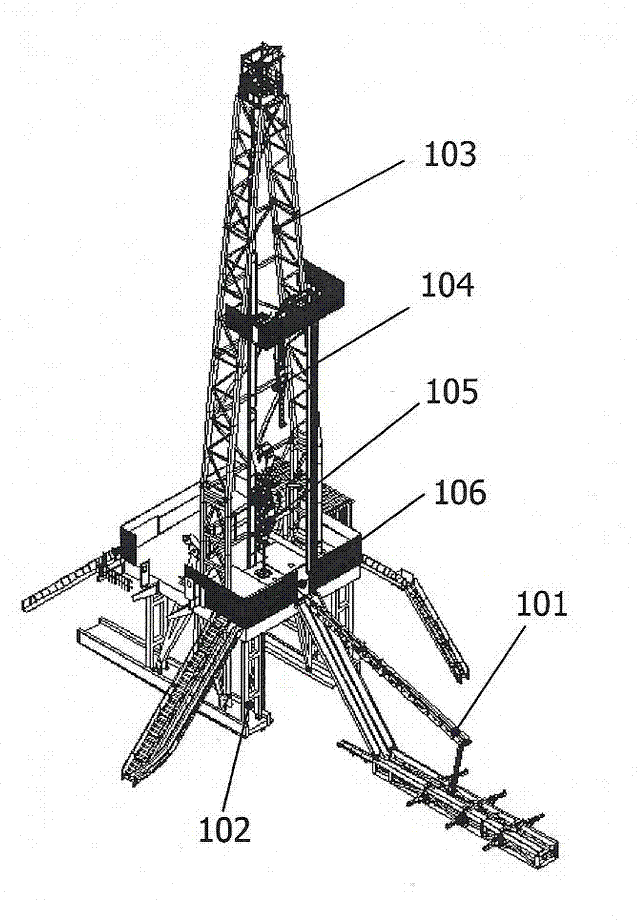
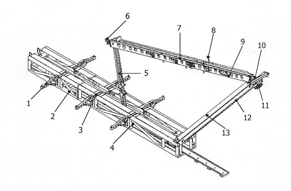
[0027] see Figure 1 to Figure 12 As shown, the present invention is composed of a drill pipe support 1, a platform 2, a turnover mechanism 3, a slideway luffing mechanism 4, a strut mechanism 5, a drill pipe push mechanism 6, a drill pipe ejection mechanism 7, an anti-fall mechanism 8, Lifting slideway 9, angle-changing mechanism 10, lifting tackle 11, chain 12 and ramp 13 form.

[0028] Platform 2 uses a two-stage approach, such as Figure 4 As shown, the front platform 303 and the rear platform 301 are connected by a positioning pin 302, and the platform 2 adopts a truss structure, which has a strong structural bearing capacity and can be disassembled for convenient transportation.

[0029] Lifting slideway 9 is divided into front and rear two sections, as Figure 5 As shown, the front lift slideway 401 is connected to the rear lift slideway 403 through bolts 402 . A drill pipe pushing mechanism 6, a drill pipe ejecting mechanism 7, and an anti-fall mechanism 8 are insta...


PUM


Abstract

The invention discloses an all-hydraulic automatic drilling tool conveying device for a deep-well drilling rig, which includes brackets, a platform, a turning board mechanism, a slideway luffing mechanism, a support rod mechanism, a pushing mechanism, an ejection mechanism, an anti-falling mechanism, a lifting slideway, a variable-angle mechanism, a lifting pulley, a chain and a ramp, and is used for being combined with a top drive and conveying a drilling tool from ground to a base platform, wherein the platform and the lifting slideway adopt a parted structure; stepped rolling paths are designed on the brackets; the brackets are hinged on the two sides of the platform; and a proximity switch is mounted in a stop pin of the drilling tool, and is used for automatically controlling the turning board mechanism. A driving chain transmission mechanism of the lifting pulley or a rack and pinion mechanism is used for lifting the slideway, a buffering power-assisting oil cylinder is equipped, and a double-shaft tilt sensor is utilized to detect and adjust the pose of the slideway and guarantee the stable running; a double hydraulic-motor driving chain transmission mechanism is used for pushing the drilling tool; and the device adopts the electromechanical and hydraulic integrated control, and has high operating efficiency and precision, as well as excellent stability.

Description

technical field [0001] The invention relates to an automatic drill pipe moving device for a land deep well drilling rig, which is used for transporting ground drilling tools to a drilling platform, in particular to a fully hydraulic automatic drilling tool transport device for a deep well drilling rig. Background technique [0002] The automatic processing device for pipes of land drilling rigs plays a vital role in improving the automation of land drilling rigs. The conventional catwalk used by land deep well drilling rigs does not yet have the function of automatically moving the ground drilling rig to the drilling floor, which not only directly affects the stability and production efficiency of the drilling system, but also has high labor intensity for workers and low production safety. . The fully hydraulic automatic drilling tool transport device is commonly known as a catwalk, but its structure and function are more complicated than ordinary catwalks. It is mainly us...

Claims


Application Information

Patent Timeline
IPC IPC(8): E21B19/14
Inventor 孙友宏吕兰于萍张春鹏刘文东王清岩张鹏张飞宇
Owner JILIN UNIV
Learn More