Blade-type energy recovery shock absorber

A technology of energy recovery and shock absorber, which is applied in the direction of spring/shock absorber, machine/engine, vibration suppression adjustment, etc. It can solve the problems of low efficiency of the energy feeding system, inferior to passive suspension, and the influence of the internal clearance of the transmission system, etc. , to achieve high energy recovery efficiency, improve driving comfort, and simple structure

Inactive Publication Date: 2013-02-13
WUHAN UNIV OF TECH +1
View PDF6 Cites 13 Cited by
  • Summary
  • Abstract
  • Description
  • Claims
  • Application Information

AI Technical Summary

Problems solved by technology

The rack-and-pinion or ball screw type uses mechanical devices to convert linear motion into rotational energy recovery systems. The disadvantage is that the frequency response function of the system to high-frequency signals is not zero due to the influence of the internal clearance of the transmission system.
For example, when the ball screw type is in the low frequency range and the ground excitation amplitude is large, its energy recovery efficiency and suspension characteristics are better; but when the system frequency is high, its suspension characteristics are not as good as passive suspensions, and energy cannot be recovered. lead to lower overall system efficiency
[0007] In the above technology of converting linear motion into rotation, the motor and the transmission system are connected in a solid state, which causes the motor to continuously change the rotation direction and repeat the motor speed from 0->acceleration->deceleration->motor speed 0 as the system vibrates cycle, creating a large "inertia loss"
This will not only greatly shorten the life of the generator, but also make the generator have little or no time to generate electricity during the entire vibration process, resulting in low efficiency of the entire energy feeding system, so that it cannot be applied to practical applications

Method used


Image

  • Blade-type energy recovery shock absorber
  • Blade-type energy recovery shock absorber

Examples


Embodiment Construction

[0029] The present invention will be further described below in conjunction with the embodiments and accompanying drawings, but is not limited to the content described below.

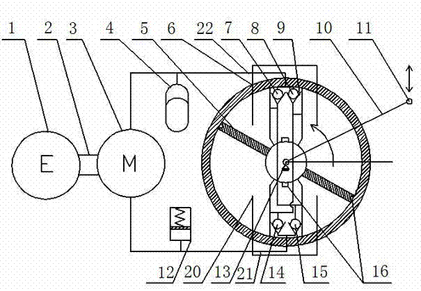
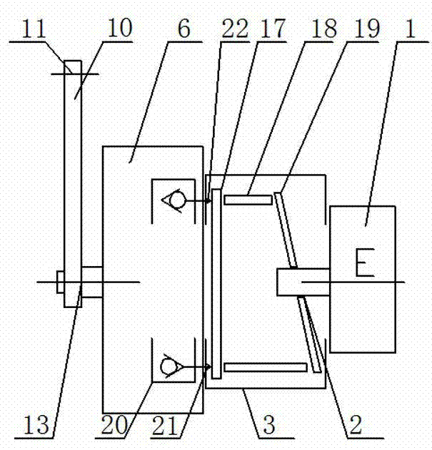
[0030] The vane type energy recovery shock absorber provided by the present invention is based on the traditional tracked vehicle vane type shock absorber, plus a set of energy recovery mechanism, which can increase energy feedback function and damping force control without changing the original vehicle structure function to improve the fuel economy and ride comfort of tracked vehicles.

[0031] The energy recovery mechanism such as figure 1 and figure 2 As shown, it includes a generator 1 , a hydraulic motor 3 , a hydraulic circuit system 20 , an airbag accumulator 4 , and a mechanical accumulator 12 . This special tracked vehicle shock absorber can convert the linear motion between the sprung mass and the unsprung mass of the suspension system caused by uneven ground into a hydraulic flow that does...


PUM


Abstract

The invention relates to a blade-type energy recovery shock absorber which utilizes a machine-electricity-fluid mixed system. The blade-type energy recovery shock absorber comprises a generator, a hydraulic motor, an energy accumulator, a hydraulic check oil way and a blade-type shock absorber assembly. By adopting the shock absorber, the linear motion between sprung mass and unsprung mass of a suspension system caused by unevenness of the ground is changed into hydraulic flow with invariable direction to drive the hydraulic motor to rotate, the hydraulic motor drives the generator to generate electricity, so that the vibration mechanical energy is converted into electric energy and recycled; the hydraulic check oil way consists of a hydraulic pipeline and a check valve system; the damping force required by the shock absorber system is mainly provided by the counter-acting force of counter electromotive force generated during operation of the generator, and active or semi-active control on the damping force of the shock absorber is realized by controlling the load of the generator. The blade-type energy recover shock absorber can be applied to a tracked vehicle in replacement of a traditional blade-type shock absorber, and is especially suitable for tracked vehicles with large electrical load. The vibration energy is recovered while the driving comfort is improved.

Description

technical field [0001] The present invention relates to a shock absorber, in particular to a blade-type energy recovery shock absorber used in the suspension system of a crawler vehicle, which has the function of recovering part of the vibration energy, and can also realize active or semi-active suspension system control. Background technique [0002] When the vehicle is running on the road, the bumps of the road and the acceleration and deceleration of the vehicle, steering and other operations will cause relative vibration between the sprung mass and the unsprung mass, and the shock absorber converts this part of mechanical energy into heat energy consumption in the form of friction Dissipate, thereby attenuating the vibration of the vehicle. If these energies can be recycled, the energy consumption of vehicles can be reduced, thereby achieving the purpose of saving energy. The present invention is just based on such an idea, that is, replacing the traditional shock abso...

Claims


Application Information

Patent Timeline
IPC IPC(8): F03G7/08F16F15/023
CPCF03G7/08
Inventor 过学迅徐琳资小林张杰方志刚袁龙宋涛张成才杨波
Owner WUHAN UNIV OF TECH
Why Eureka
Try Eureka