
Three-dimensional oligodynamic convection heat transferring LED (light emitting diode) lamp

A technology of LED lamps and micro power, applied in lighting and heating equipment, semiconductor devices of light-emitting elements, cooling/heating devices of lighting devices, etc., can solve the problems of narrow internal space of LED lamps, attenuation of LED light source chip life, ventilation and heat dissipation Poor performance and other problems, to achieve good heat dissipation effect, small external restrictions, and improve structural stability

Active Publication Date: 2013-02-13
SICHUAN SUNRAIN SIGN & DISPLAY SYST
View PDF6 Cites 1 Cited by
  • Summary
  • Abstract
  • Description
  • Claims
  • Application Information

AI Technical Summary

Problems solved by technology

[0004] 1. The performance of ventilation and heat dissipation is not good, the heat is easy to gather inside the shell, and it is difficult to fully dissipate to the outside;
[0005] 2. All components of LED lamps are fastened and connected by bolts, which is inconvenient for disassembly and assembly, and the efficiency is low, and a large operating space needs to be reserved for receiving tools such as screwdrivers;
[0006] 3. The internal space of LED lamps is small, and it is difficult to put in modules such as power supply, and the internal temperature of the housing is high and the heat is large. If a power supply with a large calorific value is placed inside the housing, the work inside the housing will be further improved. temperature, resulting in the attenuation of the life of the LED light source chip
[0007] 4. In gas stations, street lighting and other occasions, when several LED lamps need to be assembled in succession, the existing structure can only be assembled one by one and then positioned and installed separately. The assembly process is complicated and the efficiency is low.

Method used


Image

  • Three-dimensional oligodynamic convection heat transferring LED (light emitting diode) lamp
  • Three-dimensional oligodynamic convection heat transferring LED (light emitting diode) lamp
  • Three-dimensional oligodynamic convection heat transferring LED (light emitting diode) lamp

Examples


Embodiment 1

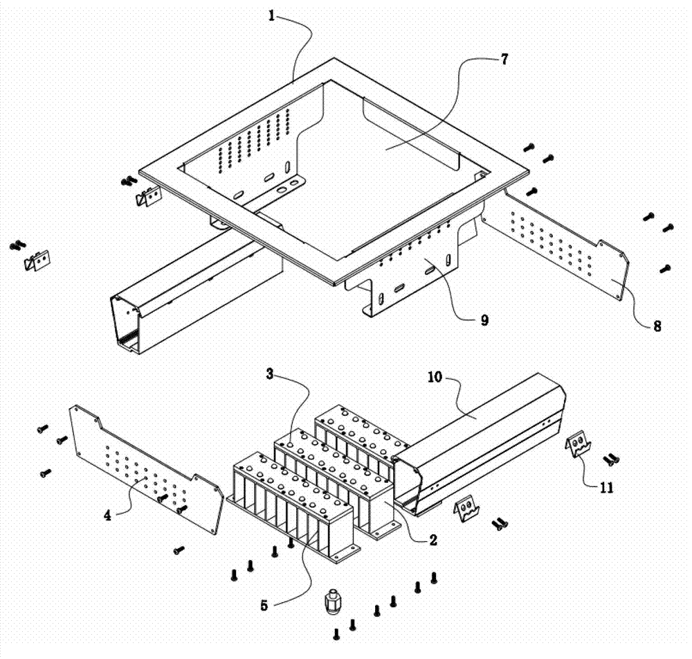
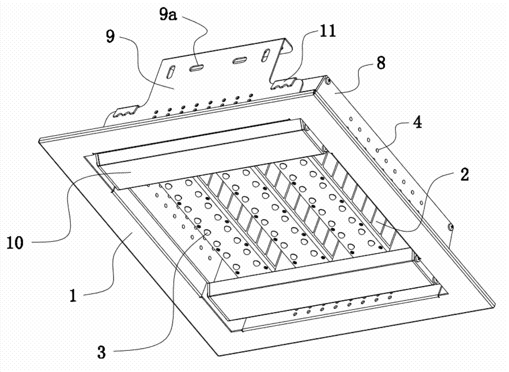
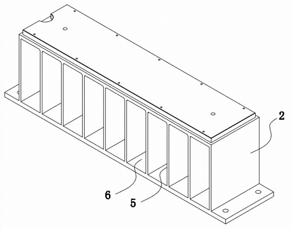
[0041] Such as Figure 1 to Figure 10As shown, the micro-power cooling, heat, convection, heat dissipation and dust-resistant LED lamps of this embodiment include a housing 1 and a radiator arranged in the middle of the housing 1. The housing 1 can be connected to an external substrate (such as a roof, a wall, etc.), Several LED light source chips 3 are arranged on the heat sink, the heat sink is a sheet radiator 2, the side of the housing 1 is provided with ventilation holes 4, and the sheet radiator 2 is provided with several The heat exchange channels 6 separated by the vertical fins 5 are arranged towards the ventilation holes 4. The interior of the housing 1 communicates with the outside world through the ventilation holes 4 to dissipate heat. The opening direction of the heat exchange channel 6 is consistent, the air convection is formed inside the housing 1 and between the vertical fins 5 of the radiator, the air inside and outside the housing 1 circulates, and the heat...

Embodiment 2

[0045] Such as Figure 1 to Figure 10 As shown, in this embodiment, in order to further simplify the connection structure and improve the efficiency of disassembly and assembly, two profiles 10 are arranged in the rectangular frame, and the profile 10 and the hanging plate 9 are arranged on the same side of the rectangular frame, as Figure 7 As shown, the profile 10 is in the shape of a cuboid as a whole and extends along the sides of the rectangular frame. The two ends of the profile 10 are respectively connected to the two side plates 8. The outside of the profile 10 is provided with a hook 11. The hook 11 is snap-connected with the upper end surface of the hanging plate 9. The profile 10 in this embodiment is used as a transition piece between the rectangular frame and the radiator. The profile 10 and the hook 11 arranged on the side of the profile 10 will The radiator is card-type connected to the rectangular frame, which is easy to disassemble and assemble. In the actua...

Embodiment 3

[0052] Such as Figure 1 to Figure 10 As shown, in this embodiment, three fin radiators 2 are arranged along the extension direction of the profile 10, the bottom plate of the fin radiator 2 is connected to the top surface of the profile 10, and the two adjacent fin radiators 2 There is a gap between them. Before connecting the LED lamps to the base, according to the needs, arrange several groups of fin radiators 2 along the extension direction of the profile 10. This part of the operation can be carried out in the operating space such as the workbench, which is convenient and quick. The operation is limited by the outside world. After the heat sink is connected to the profile 10, the profile 10 can be snap-connected and hung on the rectangular frame through the hook 11. The assembly is convenient and fast.

[0053] In other embodiments, the number of fin radiators 2 arranged along the extending direction of the profile 10 can also be two, four or more, and will not be repeate...


PUM


Abstract

The invention discloses a three-dimensional oligodynamic convection heat transferring LED (light emitting diode) lamp, which comprises a shell, and a heat radiator set on the middle part of the shell, wherein the heat radiator is provided with several LED light source chips; a ventilating hole is formed on a side surface of the shell; the heat radiator is a finned radiator; the finned radiator is provided with a heat exchange channel which is separated by several vertical fins; the heat exchange channel is arranged towards the ventilating hole; by using such a structure, the interior of the shell is connected with external environment through the ventilating hole to radiate heat; when the air exchanges heat with the interior of the shell through the ventilating hole, because an air flow direction of the ventilating hole is in accordance with the direction of the heat exchange channel on the heat radiator; convection of air is formed in the shell and among vertical fins of the heat radiator; the air between interior and exterior of the shell is circulated, and the heat radiating effect is good.

Description

technical field [0001] The invention relates to an LED lamp with a radiator, in particular to a three-dimensional micro-power convection heat conduction LED lamp which is used for gas stations, street lighting and the like and needs to be extended in depth. Background technique [0002] LED lamps are semiconductor lighting lamps, which use light-emitting diodes as light sources. Because they are a solid-state cold light source, they are environmentally friendly, pollution-free, low power consumption, high luminous efficiency, and long life. [0003] Commonly used heat dissipation methods for LED lamps include forced cooling with fans, heat pipes and loop heat pipes, etc. Among them, the forced cooling with fans has a complex system and low reliability, and the heat dissipation methods of heat pipes and loop heat pipes are expensive. For outdoor use at night LED lamps usually adopt the natural convection heat dissipation method, and the heat dissipation surface is located on ...

Claims


Application Information

Patent Timeline
Patent Type & Authority Applications(China)
IPC IPC(8): F21S8/00F21V29/00F21V17/10F21Y101/02F21K9/20F21V29/76F21V29/83F21Y115/10
Inventor 王宇付正军刘刚
Owner SICHUAN SUNRAIN SIGN & DISPLAY SYST
Learn More