Garbage burning equipment with forward-pushing three-section type cooling high-pressure loss fire grate and method for burning garbage by using garbage burning equipment

A three-stage cooling and waste incineration technology, applied in combustion methods, lighting and heating equipment, incinerators, etc., can solve the problems of incinerator output, reduced operating efficiency, unreachable operation and maintenance costs, and unsatisfactory slag leakage rate. Achieve performance improvement, easy control and long service life

Active Publication Date: 2015-03-04
SHANGHAI SUS ENVIRONMENT
View PDF4 Cites 1 Cited by
  • Summary
  • Abstract
  • Description
  • Claims
  • Application Information

AI Technical Summary

Problems solved by technology

Because the operating temperature of the existing grate block itself should not be too high, in order to better cool the equipment, the equipment is moved in a row, because there can be a gap between the rows, and then the furnace can be effectively cooled by ventilation The disadvantage is that the slag leakage rate is relatively unsatisfactory, the power consumption of operation is high, the dust concentration generated after combustion is large, and the particle size is small, and the maintenance cycle of the existing three-stage grate is 4 months, which takes a long time. The operation and maintenance cost can not always reach the ideal goal. Another disadvantage is that the garbage does not roll over on the grate, and is ignited from above by the high temperature in the furnace (single-sided ignition), so the calorific value, volatile matter, There are high requirements for coking properties; when the waste value deviates from the design value, the output and operating efficiency of the incinerator will drop significantly

Method used


Image

  • Garbage burning equipment with forward-pushing three-section type cooling high-pressure loss fire grate and method for burning garbage by using garbage burning equipment
  • Garbage burning equipment with forward-pushing three-section type cooling high-pressure loss fire grate and method for burning garbage by using garbage burning equipment
  • Garbage burning equipment with forward-pushing three-section type cooling high-pressure loss fire grate and method for burning garbage by using garbage burning equipment

Examples


Embodiment Construction

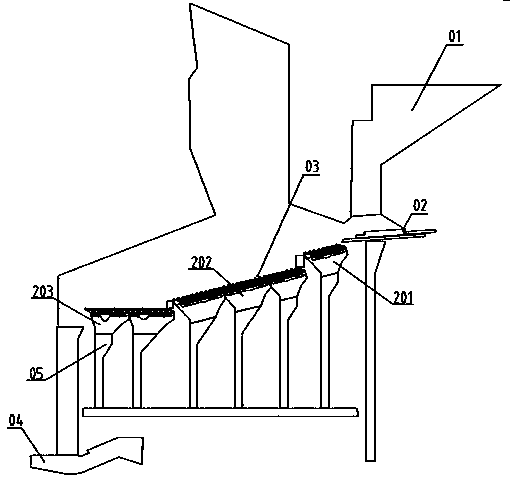
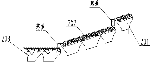
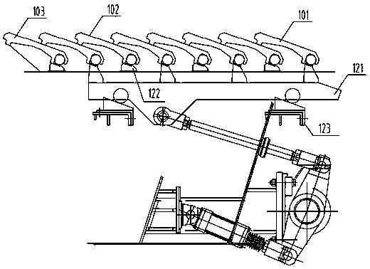
[0013] Such as figure 1 As shown in -4, a kind of waste incineration equipment that adopts three-stage cooling and high-pressure loss fire grate forwardly pushed forward, sliding fire grate 101, fixed fire grate 102 and blanking fire grate 103 are set in fire grate type waste incinerator 03; The above-mentioned grate 03 is composed of the drying section grate 201, the burning section grate 202 and the burning section furnace according to the "fixed grate, sliding grate, fixed grate, sliding grate ... the overlapping mode of the final blanking grate". Row 203. From high to low, they are arranged end to end to form a hearth. The drying grate 201 and the burning grate 202 are set at an angle of 20° to the horizontal plane; the embering grate 203 is set horizontally, which can reduce the thermal reduction rate of the slag; the material of the grate block is made of high-chromium cast steel; The grate 201 in the drying section, the grate 202 in the burning section and the grate 2...


PUM


Abstract

The invention relates to garbage burning equipment and particularly relates to a three-section type fire grate and a burning furnace with the same, i.e., garbage burning equipment with a forward-pushing three-section type cooling high-pressure loss fire grate and a method for burning garbage by using the garbage burning equipment. The garbage burning equipment comprises a drying section, a burning section and a burnout section; the forward-pushing fire grate comprises a sliding fire grate, a fixed fire grate and charging fire grates; the fire grate is composed of the sliding fire grate driven by a sliding fire grate beam, the fixed fire grate sliding on a supporting frame and fixed on the fixed fire grate beam and the charging fire grates arranged at tail ends of all the sections of fire grates; height differences exist among all the fire grate sections and among all regions; and the burnout fire grate is installed horizontally. With the adoption of the equipment, 5-6 months are taken as one repair cycle; in addition, the operating and maintaining costs are also reduced by about 80% than the initial cost, and the property is improved by 20% under the same cost.

Description

technical field [0001] The invention relates to a garbage incineration device, especially a three-stage fire grate and an incinerator thereof. Background technique [0002] Entering the 21st century, my country's environmental protection and heating industry have developed by leaps and bounds. The single-seat waste incinerator has reached 750-1000 square meters, and the demand for the capacity of the incinerator is increasing. In the past 10 years, almost all of the floor-fired waste incinerators for large-capacity heating in my country have adopted beam-type grates. The advantage of this grate is stable operation and low maintenance rate. Because the operating temperature of the existing grate block itself should not be too high, in order to better cool the equipment, the equipment is moved in a row, because there can be a gap between the rows, and then the furnace can be effectively cooled by ventilation The disadvantage is that the slag leakage rate is relatively unsati...

Claims


Application Information

Patent Timeline
Patent Type & Authority Patents(China)
IPC IPC(8): F23G5/44
Inventor 龙吉生朱晓平印晓彬石剑菁瞿兆舟张利军於志华严梦帆郭泓驿
Owner SHANGHAI SUS ENVIRONMENT
Why Eureka
Try Eureka